PDF 1.938kB
PDF 1.938kB
PDF 1.938kB

Create successful ePaper yourself
Turn your PDF publications into a flip-book with our unique Google optimized e-Paper software.
52 CHAPTER 5. RESULTS<br />
• laser_tilt_frame → laser_frame:<br />
translation: o lf = [ 0.2 0 0.1 ] T<br />
position uncertainty: σ 2 p,lf = 0<br />
The values chosen for the uncertainties are higher than they would normally be in reality to make the<br />
results more obvious. With these values it is possible to run the simulation. Nevertheless an additional<br />
frame for the laser point named laser_point_frame should be introduced. This artificial frame<br />
allows to calculate the uncertainty with the provided methods. It is assumed that the point is captured<br />
without uncertainty which of course does not hold in reality. However for the question that should be<br />
answered this assumption is feasible. Thus the transformation can be defined as:<br />
• laser_frame → laser_point_frame:<br />
translation: o lpf = [ 2 0 0 ] T<br />
position uncertainty: σ 2 p,lpf = 0<br />
5.2 Discussion of the Results<br />
To actually compare the results of the different runs, the average of the position uncertainty for one<br />
thousand transformations is used. This is an easy and sufficient enough approach to see how the tuning<br />
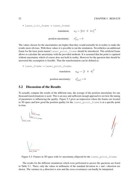
of parameters is influencing the quality. Figure 5.3 gives an impression where the frames are located<br />
in 3D space and how good the position quality for the laser_point_frame is at a specific point<br />
in time.<br />
laser_frame<br />
laser_tilt_frame<br />
torso_frame<br />
laser_point_frame<br />
base_frame<br />
Figure 5.3: Frames in 3D space with 3σ uncertainty ellipsoid for the laser_point_frame.<br />
The results for the different simulations which were performed to answer the questions are listed<br />
in Table 5.1. There, only the values in millimeter of the standard deviation in x and z-direction are<br />
shown. The variance in y-direction is zero and the cross-covariances can hardly be interpreted.