PDF 1.938kB
PDF 1.938kB
PDF 1.938kB

Create successful ePaper yourself
Turn your PDF publications into a flip-book with our unique Google optimized e-Paper software.
50 CHAPTER 5. RESULTS<br />
After defining the setup of the robot, the next step is to look at the component-based system and<br />
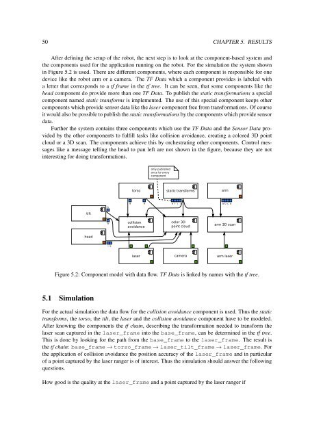
the components used for the application running on the robot. For the simulation the system shown<br />
in Figure 5.2 is used. There are different components, where each component is responsible for one<br />
device like the robot arm or a camera. The TF Data which a component provides is labeled with<br />
a letter that corresponds to a tf frame in the tf tree. It can be seen, that some components like the<br />
head component do provide more than one TF Data. To publish the static transformations a special<br />
component named static transforms is implemented. The use of this special component keeps other<br />
components which provide sensor data like the laser component free from transformations. Of course<br />
it would also be possible to publish the static transformations by the components which provide sensor<br />
data.<br />
Further the system contains three components which use the TF Data and the Sensor Data provided<br />
by the other components to fulfill tasks like collision avoidance, creating a colored 3D point<br />
cloud or a 3D scan. The components achieve this by orchestrating other components. Control messages<br />
like a message telling the head to pan left are not shown in the figure, because they are not<br />
interesting for doing transformations.<br />
only published<br />
once to every<br />
component<br />
torso<br />
static transforms<br />
arm<br />
h<br />
g g e f i l a b c d<br />
tilt<br />
h<br />
collision<br />
avoidance<br />
color 3D<br />
point cloud<br />
arm 3D scan<br />
head<br />
i k<br />
laser<br />
camera<br />
arm laser<br />
Figure 5.2: Component model with data flow. TF Data is linked by names with the tf tree.<br />
5.1 Simulation<br />
For the actual simulation the data flow for the collision avoidance component is used. Thus the static<br />
transforms, the torso, the tilt, the laser and the collision avoidance component have to be modeled.<br />
After knowing the components the tf chain, describing the transformation needed to transform the<br />
laser scan captured in the laser_frame into the base_frame, can be determined in the tf tree.<br />
This is done by looking for the path from the base_frame to the laser_frame. The result is<br />
the tf chain: base_frame → torso_frame → laser_tilt_frame → laser_frame. For<br />
the application of collision avoidance the position accuracy of the laser_frame and in particular<br />
of a point captured by the laser ranger is of interest. Thus the simulation should answer the following<br />
questions.<br />
How good is the quality at the laser_frame and a point captured by the laser ranger if