FPGA based Hardware Accleration for Elliptic Curve Cryptography ...
FPGA based Hardware Accleration for Elliptic Curve Cryptography ...
FPGA based Hardware Accleration for Elliptic Curve Cryptography ...

Create successful ePaper yourself
Turn your PDF publications into a flip-book with our unique Google optimized e-Paper software.
Ì<br />
Ì<br />
Ì<br />
Ì<br />
Ì<br />
3.4. FINITE FIELD ARITHMETIC 24<br />
can be added to the intermediate result. This leads to approximately k+ additional e)'U 3 gates <strong>for</strong> a<br />
! #" 8<br />
design. In general, an optimized multiplexer structure leads to the following resource requirement:<br />
3 K+ˆ 6 + -!-e 3$#YZK+ˆ 6 k+ v<br />
<br />
€ 3 K+ˆ 6 k+<br />
e('U<br />
3.4.6 Interleaved Polynomial Reduction<br />
A first naive design approach may per<strong>for</strong>m the polynomial reduction after the calculation of the complete<br />
multiplication. According to Eqn. 2.9, such a architecture would requirek( ) >#e('U 3 gates. Furthermore,<br />
this would lead to datapaths and multiplexers of sizek( _ c . To keep the datapaths on a maximum size of<br />
( a method of interleaved reduction has been developed.<br />
When utilizing the MSK multiplication scheme <strong>based</strong> on + a -bit CKM the maximum degree of each<br />
intermediate is( )Q+ result with+/. ( , . only( )Q+ There<strong>for</strong>e, bit values have to be reduced in each<br />
iteration. Regarding this fact Eqn. 2.9 reads as<br />
} 6 = Yª ô Ì<br />
Ò ±K5 ± Ü = Y<br />
±ÈÇÉ® Ò ±z5 ± ) P Yª ô<br />
±ÈÇÉ®<br />
±–Ç Ò ±CK5 ±. ),5 㪠±. Í7ÏÐ <br />
@ (3.1)<br />
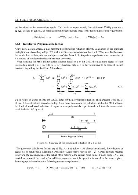
which results in a total of onlyk+]e('U 3 gates <strong>for</strong> the polynomial reduction. The particular terms (1...3)<br />
of Eqn. 3.1 are structured according to Fig. 3.5 in order to calculate the reduction. Within the MSK scheme,<br />
this kind of interleaved reduction of degree ( )²+ polynomials is per<strong>for</strong>med each time the intermediate<br />
result is shifted left by+ bit.<br />
n−1 0<br />
(1)<br />
n−1+m<br />
(3)<br />
n−1+m<br />
(2)<br />
n<br />
n<br />
6 = Y<br />
±ÈÇÉ®#Ò ±5 ±<br />
±–ÇÉ®Ò ±ª 5 㪠±<br />
±ÈÇÉ®Ò ±ª 5 ±<br />
) ô Y<br />
) ô Y<br />
åYºæ<br />
å3 æ<br />
å8 æ<br />
¢ £h¤ ¥<br />
¢ £h¤ ¥<br />
¢ £h¤ ¥<br />
Result Register (n bit)<br />
Figure 3.5: Structure of the polynomial reduction of(*),+ bit<br />
The gatecount calculation <strong>for</strong> part (f) of Fig. 3.2 is as follows: As already mentioned, the reduction of<br />
degree()*+ polynomials takesk+!e)'pU 3 gates. Additionally,+<br />
¯(:K(œ@ ñ + _ Fe)'U 3 gates are required<br />
to per<strong>for</strong>m the accumulation of the actual MSK pattern to the current result value. Finallyþk(D"!ƒe 3$#Y are<br />
needed to choose if the result of an addition, square or multiply operation is stored in the result register.<br />
Summing up, this results in the following resource requirement:<br />
npn%K(b 6 ( e('U 3 K+ˆ 6 + ¯(:K(œ@ ñ + _ `)?k+ -!-e 3$#YBK(b 6dñ (