
Create successful ePaper yourself
Turn your PDF publications into a flip-book with our unique Google optimized e-Paper software.
<strong>TM</strong>/<strong>TM</strong>C/RM/RMC-<strong>2030GE</strong><br />
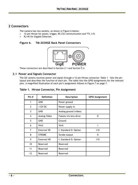
2 Connectors<br />
The camera has two sockets, as shown in Figure 6 below:<br />
• 12-pin Hirose for power, trigger, RS-232 communication and TTL I/O.<br />
• RJ-45 for Gigabit Ethernet.<br />
Figure 6.<br />
<strong>TM</strong>-<strong>2030GE</strong> Back Panel Connectors<br />
These connectors are described in Section 2.1 and Section 2.2.<br />
2.1 Power and Signals Connector<br />
GigE<br />
The GE camera receives power and signal through a 12-pin Hirose connector. Table 1 lists the pin<br />
layout and describes the function of each pin. The table lists the GPIO assignments for the relevant<br />
pins. A magnified illustration of each pin’s assignment follows in Figure 7 on page 7.<br />
Table 1. Hirose Connector, Pin Assignment<br />
POWER<br />
Pin # Definition Description GPIO Assignment<br />
1 GND Power ground<br />
2 +12V DC Power supply in<br />
3 GND Analog ground (video)<br />
4 Analog Video FoAuto iris lens drive O<br />
5 GND Ground<br />
6 Vinit Vinit I<br />
7 External VD I: Standard O: Option I/O<br />
8 STROBE Strobe output O<br />
9 External HD I: Standard O: Option I/O<br />
10 Reserved Reserved<br />
11 Reserved Reserved<br />
12 Reserved Reserved<br />
- 6 -<br />
Connectors