Manual - E-LAB Computers
Manual - E-LAB Computers
Manual - E-LAB Computers

Create successful ePaper yourself
Turn your PDF publications into a flip-book with our unique Google optimized e-Paper software.
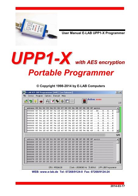
User <strong>Manual</strong> E-<strong>LAB</strong> UPP1-X Programmer<br />
UPP1-X with AES encryption<br />
Portable Programmer<br />
© Copyright 1998-2014 by E-<strong>LAB</strong> <strong>Computers</strong><br />
WEB: www.e-lab.de Tel: 07268/9124-0 Fax: 07268/9124-24<br />
2014-03-17
UPP1-X In-Circuit Programmer with USB-2<br />
Table of Contents<br />
OVERVIEW................................................................................................................................................... 4<br />
FEATURES ................................................................................................................................................... 4<br />
CONNECTIONS ........................................................................................................................................... 5<br />
SOFTWARE ................................................................................................................................................. 6<br />
AVRProg ................................................................................................................................................. 6<br />
Call options ......................................................................................................................................... 9<br />
Button-Bar ........................................................................................................................................ 11<br />
Functions of Buttons and Menus ...................................................................................................... 12<br />
Encrypt Menu .................................................................................................................................... 21<br />
AES PAC files for ISP3-X + UPP1-X + UPP2-X ............................................................................... 25<br />
Programming directly ........................................................................................................................ 26<br />
Project download .............................................................................................................................. 27<br />
Programming using the SD card ...................................................................................................... 28<br />
States, Error Display and Problems ................................................................................................. 29<br />
Building Project Files for UPP1 programmers .................................................................................. 30<br />
PackProg .............................................................................................................................................. 31<br />
Project Import ................................................................................................................................... 31<br />
Searching for Programmer ............................................................................................................... 32<br />
Project Check ................................................................................................................................... 32<br />
Program ............................................................................................................................................ 32<br />
Device Check ................................................................................................................................... 32<br />
Verify ................................................................................................................................................. 33<br />
Setup Menu ...................................................................................................................................... 33<br />
Project Download ............................................................................................................................. 34<br />
Programming using the SD card ...................................................................................................... 34<br />
Command line parameters ............................................................................................................... 34<br />
Return Codes ................................................................................................................................... 34<br />
Telnet Interface ................................................................................................................................. 35<br />
STAND ALONE MODE (PC not connected) ............................................................................................ 37<br />
UPP DOCKING STATION .......................................................................................................................... 38<br />
Status and Control lines ..................................................................................................................... 39<br />
Layout Docking Station ...................................................................................................................... 40<br />
Schematic Docking Station ................................................................................................................ 40<br />
DLL REMOTE CONTROL ......................................................................................................................... 41<br />
EXTERNAL HARDWARE .......................................................................................................................... 42<br />
Miscellaneous Adaptors ..................................................................................................................... 42<br />
TARGET POWER SUPPLY ....................................................................................................................... 43<br />
MULTIPLE PROGRAMMERS ................................................................................................................... 43<br />
BATTERY OPERATION............................................................................................................................. 44<br />
USB DRIVERS ........................................................................................................................................... 45<br />
FIRMWARE UPDATE ................................................................................................................................ 46<br />
ADDENDUM ............................................................................................................................................... 48<br />
2 · Table of Contents E-<strong>LAB</strong> <strong>Computers</strong>
UPP1-X In-Circuit Programmer with USB-2<br />
XMega ....................................................................................................................................................48<br />
TINY4-5-9-10-20 ....................................................................................................................................49<br />
Chipcon .................................................................................................................................................50<br />
Chipcon Evaluation Boards ...............................................................................................................51<br />
AT89LPxx ..............................................................................................................................................53<br />
Renesas R8C ........................................................................................................................................54<br />
OTHER E-<strong>LAB</strong> PROGRAMMERS..............................................................................................................55<br />
E-<strong>LAB</strong> <strong>Computers</strong> Table of Contents · 3
OVERVIEW<br />
UPP1-X In-Circuit Programmer with USB-2<br />
In-Circuit Programming (ISP or JTAG) is the technology of the future, at least for small and medium series<br />
electronic components with embedded processors. With SMD parts there is the problem of programming<br />
because many expensive and specialized adapters are required. An additional advantage of ISP/JTAG is the<br />
practically unlimited reprogrammability of the CPU’s.<br />
This UPP-Programmer is distinguished by minimum size, extensive software and ease of use.<br />
This manual is only valid for the UPP1-X versions of programmers.<br />
FEATURES<br />
· Connection to the PC through a USB port. USB2, USB1 and Hubs supported<br />
· No power supply necessary. The unit is powered directly from PC interface (USB) or the target.<br />
· Adapts automatically to the target’s voltage (1.8-5.5Volt)<br />
· Minimum voltage 3.3V if powered from the target system<br />
· Power consumption 40..60mA if powered from the target system<br />
· Easy and extensive software. A project can be stored on the included micro-SD card.<br />
· Software runs under Windows XP, Vista and WIN7/8, 32 and 64bit<br />
· Small, lightweight and handy unit - 110x55x20mm<br />
· Supports all SPI, JTAG, PDI and TPI programmable AVRs<br />
· Supports the SPI programmable AT89Sxx types<br />
· Supports the Atmel AT89LPxx family<br />
· Supports the ChipCon CC1110, CC2510 und CC2430 family<br />
· Supports the Renesas R8C family<br />
· Programmable supply voltage (source) for the target system 30mA..300mA 1.8..5.5Volt<br />
· Extremely fast, programs a full Mega128 in 3sec (JTAG) and a Tiny44 in 1sec (16MHz)<br />
· Self update feature via the PC<br />
· Supports JTAG, SPI, PDI and TPI programming<br />
· Very well suited for production programming by using high secure AES encryption<br />
· Processes AES encrypted project files (PAC) onboard<br />
· Supports programming cycles limitation with AES-PAC files<br />
· UPP1 devices with the Option “S“ provide a project selection out of 10 stored projects on the micro-SD<br />
card through a rotary selection switch on the bottom side of the unit. This is very useful and has many<br />
advantages for portable (offline) operation.<br />
· With the optional Docking Station and UPP1 devices with the Option „D“ the programming can be<br />
remotely controlled via control lines. Up to 16 projects on the flash card can be handled (1 of 16).<br />
· micro-SD card included. FAT16 up to 2GB and FAT32 up to 32GB and SDHC types are supported.<br />
· external switching power supply with 5Volt/800mA included<br />
· Option Battery Pack 1200mAh 5V/600mA (not included), but included with version S<br />
· Option adapter from Atmel 6pol SPI to Atmel 10pol programming connector (not included)<br />
· Option adapter from E-<strong>LAB</strong> JTAG to Atmel JTAG programming connector (not included)<br />
· Option adaptor from E-<strong>LAB</strong> UPP1-X to ChipCon CC2430 Evaluation Board (not included)<br />
4 · Features E-<strong>LAB</strong> <strong>Computers</strong>
CONNECTIONS<br />
UPP1-X In-Circuit Programmer with USB-2<br />
XP, Vista or WIN7/8 is required. An USB-1 or USB-2 port is required. With an USB-1 port the programming<br />
time will be increased somewhat.<br />
The included USB cable must be connected to a free USB connector on the PC. The USB drivers must be<br />
installed once in order to work properly. See the USB section at the end of this manual.<br />
The internal voltage is 3.3Volt. Don’t apply high loads at the target pins used for programming. No capacitors<br />
are allowed at these pins. Capacitors at the RESET pin must not exceed 100nF. With XMegas no capacitor is<br />
allowed at reset. Here the pullup should not be lower than 100kOhm.<br />
The definition of the 6-pin target plug (0.1 inch pitch male header, dual inline) conforms to a recommendation<br />
from Atmel. The TOP VIEW onto the connector of the Target is below:<br />
CPU MISO (TxD) o1 2o VCC PDI_DAT o1 2o VCC (3.3V)<br />
CPU SCLK<br />
o3 4o<br />
CPU MOSI (RxD)<br />
o3 4o<br />
/RES o5 6o GND RESET/PDI_CLK o5 6o GND<br />
Top View AVR SPI header<br />
Top View XMEGA PDI header<br />
Pin 1 of the 6-pin plug of the programmer can be located by a<br />
small triangle on the front of it. A misalignment of the plug leads to<br />
malfunction and can possibly DESTROY the unit.<br />
The working voltage of the Target CPU must be in the range of<br />
1.8V..5.5V. If this voltage is below 3.3V the UPP must be supplied<br />
by the PC or an external power supply.<br />
None of the 4 control lines of the device must be shorted. Although<br />
these lines are overload protected continuous short<br />
circuits can destroy the programmer permanently.<br />
Only electrical tested boards should be connected.<br />
JTAG programming<br />
For JTAG programming of the target CPU the 6-wire ribbon cable must be<br />
replaced by 10-wire type. Because the programmer uses the same plug for<br />
ISP and also for JTAG programming, the JTAG plug on the target system<br />
differs from the original Atmel JTAG plug. See the schematic on the left.<br />
On the left is the recommended E-<strong>LAB</strong> plug connection which must be used<br />
for the target system if the JTAG interface of the target AVR is to be used for<br />
programming. Please also note that the /RESET line should be connected to<br />
the target CPU.<br />
Top View AVR JTAG header<br />
TPI_DAT o1 2o<br />
o3 4o<br />
VCC (5V)<br />
TPI_CLK<br />
/RES o5 6o GND<br />
Top View AVR Tiny TPI header<br />
Tiny 4, 5, 9, 10, 20 TPI programming<br />
These Tinys must be programmed with 5V through 3 pins.<br />
The programming mode is called TPI. Because the same<br />
programming plug is also used by the SPI mode the plug on<br />
the target system differs from the Atmel plug.<br />
The load at the TPI_DAT pin must not be lower than 80kOhm.<br />
E-<strong>LAB</strong> <strong>Computers</strong> Connections · 5
UPP1-X In-Circuit Programmer with USB-2<br />
SOFTWARE<br />
There are two supplied programs that can be used to control the UPP1-X programmer. The first is<br />
AVRProg.exe which is the more extensive program that can be used for creating a project, editing/viewing the<br />
data and selecting fuse, lock and programmer setup options, such as power supply, programming and<br />
verifying the target and creating packed or encrypted programming files for use elsewhere.<br />
The second program is PackProg.exe and it can only be used for programming or verifying using a packed or<br />
encrypted file that has been previously created by AVRProg. It is the most suitable program for production use<br />
and is described later in this manual.<br />
The UPP1 can also be used in Stand Alone mode (ie without a PC attached) and this is described later.<br />
AVRProg<br />
AVRProg can be executed from within the AVRCo IDE (PED32) and in this mode all the project settings are<br />
passed directly from the IDE. It can also be executed directly from a shortcut or the Start Menu. In this mode<br />
an existing project has to be opened or a new one created so the project select dialog is opened on startup.<br />
Open Existing Project: A project can be opened and loaded by a double click on the desired entry or by a<br />
single click on the entry and an additional click on the Load button. All project related parameters and files are<br />
loaded.<br />
Details of the highlighted project<br />
from the select window with CPU<br />
type.<br />
Accompanying project path.<br />
The Flash Hexfile with file<br />
extension.<br />
EEprom file with extension<br />
XMega UserRow with extens<br />
Store changed or new project.<br />
Commands<br />
Build a new project<br />
Delete a project<br />
Edit an existing project<br />
Search project on network<br />
Load a project<br />
Exit this dialog.<br />
With each project it is possible to store a text comment. See ‘Comment’ dialog below.<br />
Build a new project: Select the desired target page of the tabbed notebook. Click button New. Type the<br />
desired name into the field Project Name. Click to the field Directory. From the appearing dialog select the<br />
desired directory. Now the dialog for selecting the file extensions and file types appears. Select/edit<br />
extensions and file types. The Flash file dialog appears. Select the file which contains the Flash contents.<br />
Finally the CPU type must be selected from the CPU-Select dialog. Up to here the selections are a must. The<br />
following dialog for selecting an EEprom file can be ignored, if nothing exists. The new project must be stored<br />
by the Save button.<br />
6 · AVRProg Software E-<strong>LAB</strong> <strong>Computers</strong>
UPP1-X In-Circuit Programmer with USB-2<br />
Dialog for the file types and extensions of a project.<br />
These parameters are project related and must be<br />
defined for each new project.<br />
Editing an existing project: Click the button Edit.<br />
The program is now in edit mode. With a click onto<br />
the items and fields the accompanying dialog opens.<br />
After all changes are done, store them with a click<br />
onto the Save button.<br />
Moving a project from one page to another page of the notebook is very simple. Select the project, enter the<br />
edit mode, switch the notebook page to the desired page and then store the project with the save button.<br />
Comment Editor<br />
A right click to an entry in the project select/load<br />
dialog opens this Comment dialog.<br />
With this dialog it’s possible to add or view a<br />
comment for each project.<br />
Dialog for CPU Selection<br />
If a project is being created<br />
initially or an existing project<br />
must be changed, first the<br />
CPU type must be defined.<br />
This is the purpose of this<br />
selection dialog.<br />
The CPU types LPC, TMS<br />
and PIC are not implemented<br />
at this time.<br />
E-<strong>LAB</strong> <strong>Computers</strong> AVRProg Software · 7
UPP1-X In-Circuit Programmer with USB-2<br />
Device state dialog<br />
After selecting the CPU the clock-frequency of the target must be set. To do this, the button opens the<br />
Device State Dialog. The dialog shows the parameters of the PC-loaded project and the parameters of<br />
the hex-files loaded.<br />
Editable parameters are located<br />
in the Environment group.<br />
The clock defines the SPI speed<br />
for ISP programming and can be<br />
changed every time. If this value<br />
is too high, the programming can<br />
fail.<br />
For JTAG, TPI, PDI programming<br />
mode this value has no meaning.<br />
But this parameter should have<br />
always the correct value.<br />
The voltage field on the right of it<br />
reflects the current voltage value<br />
which the ISP programmer<br />
measures on the target board, if<br />
connected.<br />
The current field selects the maximum allowed current to supply. 0.0mA sets the internal supply to the off<br />
state. The other values enable the ISP-internal supply. If a current > 0mA is selected the desired supply<br />
voltage can be selected in the voltage field. If enabled the UPP1-X programmer supplies the selected voltage<br />
to the target system (only in programming state). The current will be limited to the selected value.<br />
USB and Power Supply<br />
The UPP has an internal Step-Up Converter. It creates an output voltage up to 5,2V from the USB Voltage<br />
(4..4.8V).<br />
To suppy the UPP by the target its voltage must be at least 3.3V.<br />
Target voltage 3.3V 60mA<br />
4.0V 40mA<br />
5.0V 40mA<br />
The UPP1-S/D has no dedicated power supply connector. The USB connector is altenatavely<br />
used to connect a mobile phone power supply. A suitable switching suppy 5V/800mA is also<br />
delivered.<br />
The Application group shows the actual loaded project in the PC.<br />
The Programmer group shows the information about the connected programmer device: programmer type,<br />
serial number, date of production, firmware revision and the last firmware update. The last item is important<br />
because all update files start with their date-of-build yy-mm-dd. In the dialog above this is 2011, Feb, 21.<br />
So you can easily find out whether a new downloaded file from the WEB is the same or newer than the one<br />
already downloaded in the ISP.<br />
The download of an update into the ISP is described below in the section Firmware Update at the end of this<br />
manual.<br />
8 · AVRProg Software E-<strong>LAB</strong> <strong>Computers</strong>
UPP1-X In-Circuit Programmer with USB-2<br />
Call options<br />
Start with the Windows Explorer<br />
If you make a link in the Windows Explorer from the file-extension *.ispe to AVRprog.exe, a double click to<br />
a project-inifile xxx.ispe in the Explorer automatically invokes AVRprog.exe, which by itself reads the ini-file<br />
and loads the complete project.<br />
Start within the E-<strong>LAB</strong> IDE PED32<br />
The program start is already implemented into the IDE.<br />
Command line parameters<br />
With all calls of AVRprog command line switches can be appended. These are:<br />
-USB2 Only search for devices with USB2<br />
-e Automatic Device erase<br />
-p Automatic Programming Start<br />
-r Automatic Target Run<br />
-c Program exit<br />
-s No visual error messages are generated. Instead the errors are written into the file ‘ICPISP.err‘.<br />
This file then can be found in the project path or in the program directory of no parameter specifies<br />
the project path.<br />
-u0 A standard Pack File will be build<br />
-u1 An encrypted Pack File will be build<br />
-gProgSerNum If more than one Programmer is found then the Programmer with the serial number<br />
ProgSerNum is used.<br />
The order of the switches in the command line doesn’t matter. The internal processing is always done in the<br />
above order. The switches must be separated by spaces. A switch must not contain spaces.<br />
Example:<br />
C:\pppp\AVRProg.exe ProjectName –USB2 –p –c<br />
If the switch –p is active, a previous erase (-e) is not necessary because a programming process always first<br />
erases the target.<br />
If the switch –c is active, a previous Target RUN is not necessary because a program exit also releases the<br />
target.<br />
With the parameter ProjectName there are 2 possibilities. You can pass the complete path and name of the<br />
desired control file like: ‘C:files\hex\myprog.ispe’. Or only the name of the project is supplied like: ‘myprog’<br />
E-<strong>LAB</strong> <strong>Computers</strong> AVRProg Software · 9
UPP1-X In-Circuit Programmer with USB-2<br />
Return Codes<br />
0 dsOk Operation successful finished<br />
1 dsPwrDown No Target voltage<br />
2 dsPwrErr Target too high or too low<br />
3 dsFalseTyp Wrong CPU ID found<br />
4 dsProtect Target is protected by fuses<br />
5 dsNotEmpty Target is not empty after an erase<br />
6 dsVerifyErr Target or Programmer found a Verify error while programming<br />
7 dsFileError N.A.<br />
8 dsTimeOutErr USB driver returns a timeout<br />
9 dsCommError Communication problem with the Programmer<br />
10 dsNoProg Programmer not found<br />
11 dsNoProj Project not found<br />
12 dsFwLost Programmer returna an invalid firmware<br />
13 dsNotfound File, eg. Hexfile, was not found<br />
14 dsCalReq Programmer returns a lost or illegal calibration<br />
Networks<br />
Some networks, e.g. Novell, use DOS 8.1 style filenames and cannot handle the Project File Extension .ispe<br />
This can be solved by changing the corresponding entry in the INI-File of the programmer ISPISP-3.ini<br />
Example:<br />
[Settings]<br />
ProjExt=.isp<br />
Alternative programming<br />
A Pack file can be created that conatins all the project information. This can then be used with the PackProg<br />
program or transferred to the UPP SD card for Stand Alone Mode. PackProg is included in the UPP1-X<br />
programmer package and described later in this manual. This option is also useful when creating a file to<br />
send to another location for programming.<br />
10 · AVRProg Software E-<strong>LAB</strong> <strong>Computers</strong>
UPP1-X In-Circuit Programmer with USB-2<br />
Button-Bar<br />
For fast access of the functions with the mouse the program has a bar with speed-buttons. These allow fast<br />
working without the use of the menus.<br />
| | | | | | | | | | | Ý<br />
| | | | | | | | | | | Firmware-revision ----<br />
| | | | | | | | | | -display of the actual action<br />
| | | | | | | | | --- release of the reset of CPU and restart<br />
| | | | | | | | ----------- abort of the actual action<br />
| | | | | | | --------------- Flash and EEprom Verify<br />
| | | | | | ------------------ subsequent Fuse programming<br />
| | | | | ---------------------- Flash, EEprom and Fuses programming<br />
| | | | ------------------------- Chip erase<br />
| | | ----------------------------- State of the programmer and the target<br />
| | -------------------------------------- flush of the Flash- and EEprom buffer<br />
| ----------------------------------------- reload of the Flash- and EEprom buffer<br />
--------------------------------------------- another resp. new project load<br />
Download button (not shown above) is used to transfer projects to the SD card – see Project Download<br />
section below.<br />
E-<strong>LAB</strong> <strong>Computers</strong> AVRProg Software · 11
UPP1-X In-Circuit Programmer with USB-2<br />
Functions of Buttons and Menus<br />
Normally the use of the menus is not necessary. All standard operations can be started with the speedbuttons<br />
by a mouse click. Specialized operations can be found only in the menus.<br />
File Menu<br />
Edit/Load Project opens the project dialog. A new project can be<br />
build or an existing one can be opened and loaded.<br />
Save Project parameters stores the actual parameters to the isp-file<br />
Save Flash Buffer to binary File stores the Flash-Buffer into a<br />
binary file. A File-Dialog is opened..<br />
Save EEprom Buffer to binary File stores the Flash-Buffer into a<br />
binary file. A FileDialog is opened..<br />
Save Flash Buffer to binary File stores the Flash-Buffer into a hex<br />
file. A File-Dialog is opened..<br />
Save EEprom Buffer to binary File stores the Flash-Buffer into a<br />
hex file. A FileDialog is opened.<br />
Search Programmers is a support function which closes the currently opened programmer connections and<br />
then tries to find all connected programmers. See separate section below regarding Multiple Programmers.<br />
USB2 devices only disables the global programmer searching and enumerates USB2 types only. This avoids<br />
long timeouts with the COMport searching which can take several minutes if a Bluetooth virtual Comport is<br />
installed on the PC.<br />
The Project-Open button opens the project dialog. A new project can be built or an existing one can be<br />
opened and loaded.<br />
The Reload button loads the previously loaded Hex-Files again.<br />
The Flush button clears the Flash-Buffer and also the EEprom-Buffer completely to $FF<br />
The Device State button opens the Device State dialog. Description see above.<br />
12 · AVRProg Software E-<strong>LAB</strong> <strong>Computers</strong>
UPP1-X In-Circuit Programmer with USB-2<br />
Device Menu<br />
Blank Check tests the target (CPU) for unprogrammed ie<br />
empty. If the target is protected, a message is raised.<br />
Read back Flash if the target is not protected, the contents<br />
of the Flash is read back into the Flash buffer.<br />
Read back EEprom if the target is not protected, the<br />
contents of the EEprom is read back into the EEprom buffer.<br />
Read back UserSignatureRow if the target is not<br />
protected, the contents of the UserRow memory is read<br />
back into the UserRow-buffer. Only XMega.<br />
read back All if the target is not protected, the contents of the Flash and the EEprom is read back into the<br />
related buffer. With XMegas also the UserSignatureRow is read back.<br />
Verify Flash if the target is not protected, the contents of the target’s Flash is compared to the Flash buffer. If<br />
there is any difference an error message is raised.<br />
Verify EEprom if the target is not protected, the contents of the target’s EEprom is compared to the EEprom<br />
buffer. If there is any difference an error message is raised.<br />
Verify UserSignatureRow if the target is not protected, the contents of the target’s UserRow is compared to<br />
the UserRow-Buffer. If there is any difference an error message is raised. Only XMega.<br />
Verify all if the target is not protected, the contents of the target’s Flash and EEprom are compared to the<br />
related buffer. If there is any difference an error message is raised. With XMegas also the UserSignatureRow<br />
is verified.<br />
check device checks the programmer and also the target. If any there are any problems they will be<br />
displayed. If the CPU is protected only the device ID can be displayed (ID = 00 01 02).<br />
The check button has the same result as the item ‘check Device’ in the Device Menu above.<br />
E-<strong>LAB</strong> <strong>Computers</strong> AVRProg Software · 13
UPP1-X In-Circuit Programmer with USB-2<br />
Program Menu<br />
program all programs the Flash, the EEprom and also the fuse and<br />
lock bits in the manner defined at Options.<br />
program flash programs the Flash only<br />
program EEprom programs the EEprom only (not in JTAG mode)<br />
program UserSignaturRow programs the UserRow (XMega)<br />
program Fuses programs the fuse bits as defined at Options.<br />
program Lockbits programs the lockbits only<br />
erase Device erases the entire device, but not the fuse bits<br />
erase EEprom erases the entire EEprom (not in JTAG mode)<br />
erase UserSignaturRow erases the UserRow to $FF. (XMega)<br />
A click on the Erase button erases the entire chip inclusive the lock bits. Please note that the fuse bits<br />
are not erased or changed.<br />
The Program button erases the chip completely including the lock bits, then the chip is reprogrammed.<br />
The fuse and lock bits are treated as set in Options.<br />
The Security button writes the lock bits which are defined in Options. It is required that the chip is not<br />
protected until this time<br />
The Verify button starts a verify of the target with the buffers. Only possible on an unprotected device.<br />
The Stop button aborts the current action.<br />
After programming a device the reset stays active. The target can be released by a click on the Run<br />
button or again reset without disconnecting the programmer from the target.<br />
If the option autorelease target is enabled in the option dialog, the reset is always removed after<br />
a programming cycle.<br />
Options Menu<br />
All of the fuse bits and lock bits, Reset polarity etc. and also the whole behaviour of the programmer and it’s<br />
additional options must be setup at least once for a project. To do this there a two dialogs: the Options Dialog<br />
and the Target Options Dialog. These are called with the menu below.<br />
Programmer options starts the Options Dialog where the Fuse and Lock<br />
bits can/must be defined and also some other functions.<br />
Target options starts the Target Options dialog where powerful extra<br />
functions can be enabled and setup.<br />
DownLoad new Firmware starts a firmware update of the programmer.<br />
For more information take a look into the chapter Firmware Update at the<br />
end of this manual.<br />
Calibrate programmer is not applicable for the UPP1-X<br />
SD-cards size 2..32 are supported. Also SDHC types. Please use only speed grade 4 and above.<br />
For highest speed the cluster size is imortant. Godd values are<br />
up to 4GByte size -> 4kB, 8GByte size -> 8kB, 16GByte size -> 16kB, 32GByte size -> 32kB<br />
14 · AVRProg Software E-<strong>LAB</strong> <strong>Computers</strong>
UPP1-X In-Circuit Programmer with USB-2<br />
Programmer Options Dialog<br />
The Options-Dialog controls the behaviour of the programmer at erase resp. programming of the target. The<br />
types of the options depend of the Hex-files and the selected CPU-type..<br />
If, for example no EEprom-file is loaded (.EEP), the item program EEprom is disabled.<br />
If the CPU does not support ‘Fuse Bits’ the Fuse bits groups are not visible, otherwise the accessible fuses<br />
are enabled for access. The meaning of the Fuse Bits can be found in the Atmel CPU datasheets.<br />
The General group defines the common behaviour of the unit. The item blank check after erase is only<br />
necessary for testing purpose. Normally it should be disabled.<br />
Program Flash and program EEprom normally both should be enabled<br />
Ignore false ID disables the error popup in case of a false Device-ID. It is generally unadvisable to check this.<br />
Investigate why the wrong ID is being returned.<br />
Auto release Target releases the RESET of the CPU automatically after programming.<br />
Program Fuses should always be checked. Fuses are essential for the AVRs.<br />
Program Lockbits also should be checked. But it has no meaning if no Lockbit is activated.<br />
The item Security defines the lockbits for the protection modes. Lockbit0 or Lockbit1 by themselves make<br />
little sense. A complete protection of the device can only be achieved if both bits are active/checked. The<br />
BootLock bits should only be activated if the boot section in the AVR is used for booting (self program). The<br />
exact function and meaning of the fuses should be observed in the CPU datasheets.<br />
E-<strong>LAB</strong> <strong>Computers</strong> AVRProg Software · 15
UPP1-X In-Circuit Programmer with USB-2<br />
The Fusebits… group define various functions as defined by particular CPUs. e.g. Mega128, the fuse<br />
programmable internal Reset time. With other CPU types the internal oscillator or the Brown-Out can be<br />
defined. Because each CPU interprets these bits in its own way it’s impossible to make a general statement<br />
here. Some fields can be hidden if the CPU doesn’t support some fuses, otherwise the supported fuse bits<br />
can be changed by the user. Unsupported fuse bits are disabled. An empty field means that this option is<br />
disabled = 1. A green ok means that this option is set = 0 ie enabled.<br />
Attention: within the fusebit groups some CPUs have a SPIEN fuse. This fuse normally is ‘don’t care’ with<br />
SPI-Low-Voltage programming. But there are exceptions, the Tiny12 for example. In this case the SPIEN fuse<br />
must be activated. Otherwise the chip is not accessible any more.<br />
The SPIEN fuse is always programmable in the JTAG Mode. If SPIEN and JTAGEN are disabled this CPU is<br />
also not accessible any more. Note that JTAG mode commandeers some I/O pins from normal use.<br />
Sometimes it is more readable for the designer if the binary values of the fuses are shown instead of the<br />
boolean values. This can be accomplished with this button.<br />
Calibration Byte Dialoge<br />
Some CPUs which feature an internal RC-oscillator often have also up to four special read-only fuses called<br />
‘Calibration bytes’, which are shown in the field Calibration Bytes. These bytes can be used by the<br />
program/application to fine tune the internal RC-oscillator. Because this byte is unique in each CPU it must be<br />
individually passed to the application. A checked checkbox WriteCal Byte forces the programmer to read this<br />
fuse byte and store it into the Flash. The target location of this calibration byte must be supplied by the user<br />
with the help of the dialog ‘Calibration bytes’ shown below.<br />
Dependent of the CPU type there are up to 4<br />
Calibration Bytes which must be read out of the<br />
CPU. Each byte corresponds with a unique<br />
RC-oscillator. The choice of this byte (radio<br />
buttons) is dependent on the settings of the<br />
CLKSEL-fuses.<br />
With the edit field ‘address’ the target address<br />
in the Flash for this byte must be set. With<br />
CPUs up to 64kByte Flash size this can be<br />
each value > $0000. With CPUs > 64kB Flash<br />
(mega128) the selected address must be even.<br />
With newer AVRs and the use of the standard<br />
RC-oscillator a Calibration Byte handling is not necessary. These devices automatically read this byte from its<br />
EEprom memory into the OSCAL register.<br />
Attention: All Fuse and Lockbits are low active. This means if the data sheet shows a zero ‘0’ for a specific bit<br />
the corresponding field in this dialog must show a green ‘ok’. Then a ‘1’ bit must show an empty field. Atmel<br />
always uses negative logic for Fuse and Lockbits!<br />
With the field ComPort the interface to use can be selected. With an UPP1-X the setting ‘USB only’ should be<br />
preferred. If V24 (serial) programmer types can also be connected to this PC ‘automatic’ should be selected.<br />
The field Reset options defines the controlling behaviour of ISP to the target CPU. Normally all 3 items are<br />
inactive. For special target hardware the reset level can be inverted. Push/Pull reset makes sense if the reset<br />
input of the target CPU is burdened by other electronics e.g. R/C combination. But here the loadings must be<br />
reduced by a series resistor of a few kilo ohms. The reset-delay (the time a reset stays inactive before the<br />
next activation can take place) can be extended. This is only for special cases.<br />
The field Programmer Mode is only visible if the selected CPU supports SPI, JTAG, TPI or PDI<br />
programming. In this case one of these modes can be selected.<br />
16 · AVRProg Software E-<strong>LAB</strong> <strong>Computers</strong>
UPP1-X In-Circuit Programmer with USB-2<br />
XMega Options Dialog<br />
With the XMegas some options are impossible or make no sense. The dialog above is typical for an XMega.<br />
Please note that there is the checkbox program UserRow. It can only be checked when a hex file for the<br />
UserRow is present. (xxx.usr)<br />
The fuse JTAGEN can always be unprogrammed because the JTAG interface is never used here. Instead the<br />
PDI interface is always used.<br />
Some combinations in the Fusebits1, Fusebits2 and Fusebits5 can be illegal and should be avoided.<br />
Otherwise an unexpected behaviour of the CPU can result.<br />
Please note that the voltage supply is limited to 3.6V for XMegas.<br />
E-<strong>LAB</strong> <strong>Computers</strong> AVRProg Software · 17
UPP1-X In-Circuit Programmer with USB-2<br />
Power Supply<br />
The Power Supply group selects the maximum allowed current to supply. 0.0mA sets the internal supply to<br />
the off state. The other values enable the ISP-internal supply. If a current > 0mA is selected the desired<br />
supply voltage can be selected in the voltage field. If enabled the ISP programmer supplies the selected<br />
voltage to the target system. The current limiter can be set between 30mA and 300mA. The current will be<br />
limited to the selected value. Please note that PC-powered external USB HUBs may supply only 100mA.<br />
Basically this power supply is switched off after the programming cycle. If the supply shall continuously supply<br />
the target so the checkbox stay active must be checked. If in addition the auto release target is activated the<br />
target system starts up and can be tested at runtime.<br />
The editable fuse- and lock bits are displayed on the right side in the Write column and here they can be<br />
edited. The Read columns can always be updated with the Refresh button. To do this the actual fuse and<br />
lock bits are read out of the target as far as possible.<br />
The button program Fuses is very useful for erasing of illegal FuseBits, which may be activated by an<br />
accidential programming.<br />
One can try with ‘program Fuses’ to set all fuses to the desired value. Some possible error messages can be<br />
ignored in this case. In most cases the CPU then shows a ‘normal’ behaviour as expected.<br />
Attention (SPI mode):<br />
Some CPU types have an internal RC-Oscillator or the feature to connect an external RC-Oscillator.<br />
These options must be selected by some fuse-bits. Sometimes it’s also possible to select an external<br />
low-frequency quartz crystal. With selecting such an oscillator one must be very careful:<br />
1. Internal RC-oscillator.<br />
With this option selected the standard frequency is typical 1MHz. Because of this the programmer’s<br />
frequency selector must also be set to 1MHz, otherwise there will be errors with accessing the target<br />
CPU. The nominal frequency is 1MHz. With a CPU-voltage of 3Volt the frequency drops to 500kHz.<br />
2. External RC-oscillator.<br />
If this mode is activated, there must be a proper external circuit connected. Otherwise the target CPU<br />
will be never accessible.<br />
3. Low Frequency Crystal.<br />
If this mode is activated, a 32kHz watch quartz must be connected to the target. Otherwise the target<br />
CPU will be never accessible.<br />
Please note in addition, that while programming, the actual fuses in the CPU are relevant. The new<br />
programmed fuses become valid the first time after a reset. Some fuses become valid the first time after a<br />
power down.<br />
With accidentally wrongly programmed oscillator fuses it’s possible that after that the external oscillator circuit<br />
must be changed to again get access to the target CPU.<br />
The above restrictions and warnings are not relevant for JTAG, TPI and PDI programming. Here the CPU<br />
must simply be supplied with voltage/current. A working oscillator is not necessary and is ignored. But then<br />
never disable the JTAGEN fuse in JTAG mode.<br />
The settings of the Lockbits (protected/unprotected) and the voltage supply of the target by the ISP are also<br />
displayed in the main program by two symbols.<br />
The padlock means that the target will be locked/protected by the lockbits. The mains or<br />
battery symbol means that ISP must supply the target system. Both symbols belong to the<br />
actual loaded project in the PC program.<br />
18 · AVRProg Software E-<strong>LAB</strong> <strong>Computers</strong>
UPP1-X In-Circuit Programmer with USB-2<br />
Target Options Dialog<br />
This dialog has two jobs:<br />
1. Store/program of additional data into the Flash of the target.<br />
2. Serial number administration.<br />
The caption shows the name of the project present in the PC.<br />
If a project name is programmed into the target and it is<br />
readable, it is displayed in this panel. The check button write<br />
Name shows the state of this option.<br />
Serial number in target shows the read back serial number<br />
from the target, if any. The check-button write Number shows<br />
the state of this option<br />
Serial number in UPP/ISP shows the serial number in the ISP<br />
and PC. It’s incremented after every programming<br />
With Preserve Serial Number the number in the Target is<br />
read back and used for the next programming cycle.<br />
Reset all resets all options, also the serial number.<br />
ISP options enables or disables all options.<br />
CheckSum in target shows the flash check sum in the target,<br />
if present. The check-button write ChkSum shows the state of<br />
this option.<br />
CheckSum in UPP/ISP shows the flash check sum present in<br />
the ISP and PC.<br />
Storing Parameters into the target<br />
If there is enough space in the flash memory of the target CPU additional parameters and information can be<br />
placed at the end of the flash memory. With the option switches (checkboxes) of the dialog above each option<br />
can be individually enabled or disabled.<br />
A change gets saved immediately. Also these options are stored into the project’s INI-file as usual. The<br />
options, if any, are programmed at the end of a programming cycle into the last bytes of the target’s flash.<br />
At each invocation of this dialog there is a try to read the actual-parameters from the target. This operation<br />
only works, if the target is present, powered and not protected, of course. The firmware in the target CPU<br />
always has access to this data.<br />
Project Name into Flash<br />
If the checkbox write Name is activated, the ISP is enforced to write the project’s name into the flash. This is<br />
done at the end of a programming cycle.<br />
Serial Number into Flash<br />
Activating the checkbox write Number instructs the ISP to burn a serial number into the flash. The integer<br />
part of this number is then incremented. The serial number consists of 2 parts:<br />
1. Two arbitrary characters from the field Serial Number in ICP/ISP. This part stays unchanged.<br />
2. A number in the right field. This number can be zeroed with the button Reset Number or preset with<br />
a number and the Preset button.<br />
The count of the programmed targets up to now can be found here.<br />
E-<strong>LAB</strong> <strong>Computers</strong> AVRProg Software · 19
UPP1-X In-Circuit Programmer with USB-2<br />
Preserve Serial Number<br />
If the serial number is enabled then this option prevents writing a new/different number into the flash. If the<br />
target is not protected the internal number in the target is read out and is used for reprogramming the flash.<br />
This ensures that the number stays unchanged and the old one is re-used, despite of a new programming of<br />
the chip.<br />
CheckSum into Flash<br />
While downloading the flash file, a 16bit checksum is generated over this data. This number is displayed in<br />
the field CheckSum in ICP/ISP. This value can be written into the flash by checking the checkbox write<br />
CheckSum. This is done after every programming cycle. Note that the checksum contains only values from<br />
the original Flash-Hexfile. Additional parameters programmed at the end of the flash by the ISP itself are not<br />
recognized. Also empty (not addressed) parts in the hexfile are discarded.<br />
Reset All<br />
This button resets all values and options.<br />
Note: all changes are immediately stored. But they are only recognized at the next programming cycle.<br />
The application/firmware always has access to this parameters. The parameters are stored into the last 16<br />
resp. 32 bytes of the flash. The project name has a lead-in of ‘proj’. The serial number has a preamble of<br />
‘ser#’. The number is always the fourth and third last byte. The checksum, if present, always can be found in<br />
the last 2 Bytes of the flash. The order of the serial number and the checksum is loByte/hiByte. Sample:<br />
LSB MSB LSB MSB<br />
ser number checksum<br />
Attention:<br />
programming from the flash card writes the serial number on each succesfull programming cycle to the card.<br />
This means stress to the card and may damage it early. To minimize these problems one should use cards<br />
with the attribute x80.<br />
These are very fast and promise a 10 times longer lifetime for write cycles.<br />
Um einen frühzeitigen Ausfall zu vermeiden, sollten die neueren und besseren Karten Typen mit dem Attribut<br />
x80 eingesetzt werden. Diese sind wesentlich schneller und bieten eine 10 längere Lebenszeit bezogen auf<br />
die Schreib Zyklen.<br />
20 · AVRProg Software E-<strong>LAB</strong> <strong>Computers</strong>
UPP1-X In-Circuit Programmer with USB-2<br />
Encrypt Menu<br />
The first four items of the menu are not valid for the ISP3-X<br />
programmer types.<br />
The last 3 items are relevant for the ISP3-X.<br />
These menu items open an encrypt or pack dialog. With the<br />
help of one of this dialogs encrypted or packed binary files can<br />
be created which can only be read and processed with the<br />
included program PackProg.exe. All three file types can be<br />
used with an ISP3-X as the programmer expects the program<br />
PackProg.exe<br />
With packed files or projects there is a medium protection. All Hex files and also the programming control,<br />
fuses etc. are written into a binary file so the recipient does not need to have great programming knowledge<br />
and it is also impossible to change any setups, fuses or file contents.<br />
The encryption enhances a packed file in such a way that programming files can be sent to every place in<br />
the world and the recipient or others are unable to disassemble them or do any ‘reverse engineering’.<br />
Furthermore there is the additional feature to include a password into the encryption so only the right ISP3-X<br />
programmer can use this file. This is an additional protection against illegal copies.<br />
Deep<br />
encrypted files can only be used with the program PackProg.exe<br />
Standard encrypted files can be loaded into the UPP programmer types. But for use with the ISP3-X the<br />
utility program PackProg is absolutely necessary.<br />
Packed<br />
files can be loaded into the UPP programmer types. But for use with the ISP3-X the utility<br />
program PackProg is absolutely necessary.<br />
Deep encrypt Mode<br />
This mode should not be used with the new programmers (ISP3-X, UPP1-X, UPP2-X) .These use the much<br />
better AES encrytion. AES creates an extremely encrypted project that can only be read und processed with<br />
Prog.exe utility. As an option an additional password to make sure that only a specific programmer is able to<br />
process these projects. This menu shows the following dialogue:<br />
This encryption allows you to ship program data around the world without enabling the receiver or a third party<br />
to disassemble or “Re-Engineer” the contents.<br />
The encrypted file (*.enu or *.en#) contains the serial number of the target programmer. This ensures that<br />
only this specific UPP is able to process the files.<br />
To generate such a file the creator if the file must know the serial number of the target UPP.<br />
Read Key reads the serial number if the target UPP is connected to the PC:<br />
Press Read Key and the number appears in edit Password.<br />
Add Key allows adding the number to the list.<br />
If the serial number of the target programmer is unknown, its owner must use PackProg to read an exchange<br />
it with the manufacturer of the project.<br />
The manufacturer puts this number in the edit Password area.<br />
After entering a new password Add Key adds it to the list.<br />
To create the encrypted file, select the UPP number from the list (blue bar).<br />
Encrypt with PWD creates and stores the file.<br />
E-<strong>LAB</strong> <strong>Computers</strong> AVRProg Software · 21
UPP1-X In-Circuit Programmer with USB-2<br />
Encrypt w/o PWD creates a file that is not dedicated to a specific programmer.<br />
This file is encrypted but not password protected and can be processes by any UPP.<br />
Depending on the file extension the created file shows the extension *.enu or *.en0 or *.en1 etc<br />
The menu item opens the following dialogue:<br />
New passwords are added with Add Key button and deleted<br />
with Del Key button.<br />
Encrypt with PWD button creates a protection password.<br />
This ties the generated file to the programmer that<br />
generated this password.<br />
Encrypt w/o PWD button creates and stores an encrypted<br />
file without password protection<br />
Generation of an ISP3-X password is also explained in<br />
chapter PackProg.<br />
.<br />
If the target programmer is already connected to this PC<br />
button Read KEY reads its password.<br />
Standard encrypt Mode<br />
This option builds a packed and well encrypted project which only can be processed with the PackProg<br />
program in conjunction with an ISP-3 programmer type. But also a UPP programmer can directly load (using<br />
its memory card) and process such a file. As an option, a password can be included so that processing this<br />
file is only possibly by the programmer which generated the password. The menu item opens the dialog<br />
shown below:<br />
The dialog serves to set the file extension. The extension can<br />
include a number, en0..en9 for a better handling with the UPP<br />
programmer or a simple *.enu. The choice must be done with one<br />
of the file number buttons.<br />
The checkbox Dock or DLL is not relevant for the UPP1-X.<br />
22 · AVRProg Software E-<strong>LAB</strong> <strong>Computers</strong>
UPP1-X In-Circuit Programmer with USB-2<br />
If the extension was selected the dialog below opens:<br />
This dialog mainly serves to decide whether a password must be<br />
included or not. A password exclusively binds this file to this<br />
specific programmer which supplied it. If a password is<br />
necessary then it must be selected from the list field.<br />
This option must be selected by the button Encrypt with PWD or<br />
disabled with the button Encrypt w/o PWDt.<br />
If the target programmer is already connected to this PC the<br />
password can be requested. With the button Read KEY the<br />
password is read out of the programmer and displayed. With the<br />
button Add Key the new password can be appended to the<br />
password pool.<br />
This file type can be processed with the program PackProg.exe<br />
and also with all UPP programmer types.<br />
pack Project Mode<br />
This option builds a packed but not encrypted project which only can be processed with the PackProg<br />
program. A UPP programmer also can directly load and process this file type. There is no password possible<br />
and so every ISP-3 or UPP programmer can use this file.<br />
The menu item opens this dialog.<br />
The dialog serves to set the file extension. The extension can<br />
include a number, pk0..pk9 for a better handling with the UPP<br />
programmer or a simple *.pac. The choice must be done with one<br />
of the file number buttons.<br />
The checkbox Dock or DLL is not relevant for the UPP1-X.<br />
This file type can be processed with the program PackProg.exe and also with all UPP programmer types.<br />
Dock or DLL Option shos the following dialoge:<br />
UPP Version „D“ with Docking Station handles and stores more than<br />
10 projekts.<br />
These file type can also be handled and processed by PackProg.exe<br />
E-<strong>LAB</strong> <strong>Computers</strong> AVRProg Software · 23
UPP1-X In-Circuit Programmer with USB-2<br />
Procedure<br />
1. Create a project as usual or load an existing project.<br />
2. Select the proper setups and properties for this project as usual.<br />
3. Select one of the three file modes, heavy encrypted, encrypted or packed.<br />
4. The two encrypted types provide a password protection so that only this programmer which supplied<br />
the password can process it.<br />
5. Click the button ‘Encrypt’ or one of the file number buttons.<br />
6. Copy the generated file to a storage media.<br />
7. If the receiver doesn’t own the program ‘PackProg.exe’, also copy this tool and this manual onto the<br />
media.<br />
8. Ship the media to the receiver.<br />
Shipping this file(s) via email is also possible. In this case it’s a good idea to ‘zip’ all files for secure internet<br />
transport.<br />
Encryption<br />
The encryption feature uses a secure algorithm. Unfortunately up to now there is no absolutely secure<br />
(uncrackable) encryption. But the time investment to decrypt the file is so high and expensive, it’s cheaper and<br />
faster to completely start an new program from scratch J<br />
Password<br />
The program ‘PackProg.exe’ on demand reads out the internal password of a connected ISP-3 programmer.<br />
This password is only valid for this programmer and is not portable to other programmers. Because of this it’s<br />
assured that programmer files containing this password can only be programmed with this programmer.<br />
Procedure<br />
1. The chip or board programmer must install the program PackProg on the computer which will be used<br />
for the chip programming. To do so the file ‘PackProg.exe’ must be copied into the desired directory.<br />
2. The program ‘PackProg.exe’ must be started.<br />
3. The UPP1-X programmer must be connected to this PC.<br />
4. The password (displayed with the menu item ‘Setup/request Password’) must be passed to the<br />
creator of the programming files (packed or encrypted projects).<br />
5. The creator then inserts the password in the program ‘AVRprog.exe’ into his system:<br />
a. Start of ‘AVRprog.exe’<br />
b. Open the Encrypt/Pack dialog with the menu item ‘Encrypt/PackProg Encrypt’.<br />
c. Click the button ‘Add’.<br />
d. Add any comment or name into the comment field.<br />
e. Insert the password into the password field.<br />
f. Store all with the button ‘Add’.<br />
6. With files which are sent to this recipient with a password it must be clear that only the correct<br />
password must be used for the file generation. An alternative is item 7<br />
7. With the button ‘Public’ there is no password included and all recipients who have the program<br />
‘PackProg.exe’ can process this file.<br />
Programmer<br />
The program ‘PackProg.exe’ supports all programmer types ISP3, UPP1 and UPP1.<br />
Find additional information below.<br />
24 · AVRProg Software E-<strong>LAB</strong> <strong>Computers</strong>
UPP1-X In-Circuit Programmer with USB-2<br />
AES PAC files for ISP3-X + UPP1-X + UPP2-X<br />
If absolutely secure PAC files are needed for the types ISP3-X, UPP1-X or UPP2-X (‘X’ programmer) they<br />
must be created with AES encryption. AES is an absolutely secure encryption which can’t be ‘hacked’.<br />
Because the encryption can only be done in the ‘X’ programmer types, listening (sniffing) on the USB lines<br />
results in unusable data.<br />
Furthermore the AES mode has the advantage to create a PAC file for a specific programmer using its serial<br />
number so this file can’t be used on any other programmer. As an additional feature the Quantity limitation<br />
can be used. So hidden ‘black’ productions are absolute impossible.<br />
So it makes sense to use the AES encryption at least for external production. With in-house production the<br />
‘standard’ PAC file is sufficient.<br />
Standard PAC file<br />
AES PAC file<br />
To create an AES PAC it is mandatory to have an ‘X’<br />
programmer connected to the PC.<br />
The dialog for creating of an AES PAC file provides three<br />
different modes.<br />
A. Standard Encryption (only AES used)<br />
B. Encryption with password (Sernum used). Here the<br />
serial number of the target programmer is needed.<br />
It will then be integrated into the encryption and<br />
checked by the target programmer. The target<br />
programmer is not needed here, only its serial<br />
number.<br />
C. Quantity limitation (Sernum+Quantity used). Also<br />
here the serial number of the target programmer is<br />
necessary. Furthermore the maximum allowed<br />
programming cycles are preset. If this number is<br />
reached/exceeded the programmer ignores further<br />
programming attempts.<br />
The AES properties of a PAC file can be requested<br />
with the tool PackProg by ‘File Info’ from the target<br />
programmer.<br />
Attention:<br />
AES encrypted PAC files can be processed by every<br />
‘old’ programmer type (ISP3-USB, UPP1-USB,<br />
UPP2-USB) but because they are unable to decrypt<br />
such files only nonsense will be programmed.<br />
E-<strong>LAB</strong> <strong>Computers</strong> AVRProg Software · 25
Programming directly<br />
UPP1-X In-Circuit Programmer with USB-2<br />
Interactive programming must be started with this button of the PC application.<br />
The entire chip is erased including the lock bits and then totally reprogrammed. The fuse and lock bits<br />
are treated as described in Options.<br />
The MMC card is not necessary as the PC and the program has all necessary data.<br />
It is further possible to program via PC but to use a project from the MMC card.<br />
The download dialoge is opened by the<br />
button.<br />
Select the project by a click in the list box.<br />
This enables the erase, verify and pro buttons.<br />
prog Chip programs the CPU<br />
If the chip is not read protected verify Chip reads<br />
and compares the CPU with the PC memory.<br />
Print outputs a hardcopy of the list to the printer<br />
Please note that with portable use (offline) only<br />
project number 0 is available for programming<br />
UPP/S has a rotary switch on the rear that allows the<br />
selection of one from 10 possible projects.<br />
The file numbers correspond to the switch position<br />
(0..9). The arrow in the list shows the actual position<br />
of the rotary switch. Without option “S” it shows<br />
always Position.0.<br />
File Info shows the relevant parameters of the<br />
selected project.<br />
26 · AVRProg Software E-<strong>LAB</strong> <strong>Computers</strong>
Project download<br />
UPP1-X In-Circuit Programmer with USB-2<br />
The UPP programmer has several working modes. The PC-direct (Transparent Mode) mode doesn’t need an<br />
SD flash card, and all other modes use an SD card with a stored project.<br />
There are several possible ways to store a project into an SD card.<br />
Flash card Reader/Writer<br />
The PC recognizes this device as an additional removable drive.<br />
With the E-<strong>LAB</strong> control program a packed file must be compiled<br />
from all parts of the project. To do this the desired project must<br />
be loaded. Then the Encrypt menu must be opened. A click onto<br />
the item<br />
pack Project or Standard encrypt UPP opens a file dialog for<br />
storing the project in the packed format.<br />
The upper 4 items are not relevant for UPP1 devices.<br />
If the SD drive is chosen (reader/writer) the packed file is stored<br />
on the SD card.<br />
As an alternative this file can also be stored onto another media, a floppy (remember them?) or USB stick for<br />
example. Or it can be sent as an attachment of an email.<br />
Please note that with a UPP1 programmer as the target device only the options with [ISP3+UPP …] should be<br />
used. Packed files built with the option Deep encrypt never can be directly used with the UPP. The program<br />
PackProg.exe must always be used.<br />
With packed files or projects there is a medium protection. All Hex files and also the programming control,<br />
fuses etc. are written into a binary file so the recipient must not have great programming knowledge and it is<br />
not necessary but also impossible to change any setups, fuses or file contents.<br />
The encryption enhances a packed file in a way so that programming files can be send to every place in the<br />
world and the recipient or others are unable to disassemble them or do a so called „re-engineering“.<br />
Furthermore there is the additional feature to include a password into the encryption so that only the right<br />
programmer can use this file. This is an additional protection against illegal copies.<br />
Deep<br />
encrypted files can only be used with the program PackProg.exe<br />
Standard encrypted files can be loaded into the UPP programmer types<br />
Packed<br />
files can be loaded into the UPP programmer types<br />
pack Project for ISP3-X UPP1-X UPP2-X<br />
In this mode always the absolutely secure AES 128bit encryption will be used.<br />
Note:<br />
New Flash Cards must be formatted in a PC Flash drive before the first usage in the UPP. This always<br />
ensures that this card is readable in both devices, the PC and the UPP<br />
E-<strong>LAB</strong> <strong>Computers</strong> AVRProg Software · 27
UPP1-X In-Circuit Programmer with USB-2<br />
Programming using the SD card<br />
There is the additional possibility to use the PC for programming by using one of the projects which are stored<br />
on the SD card of the UPP.<br />
To do this the download dialog below must be opened with the download button.<br />
The project stored in the SD card must be selected<br />
by a click onto the entry in the list box. Now the<br />
erase, verify and prog buttons are enabled.<br />
The programming can be started with the prog Chip<br />
button.<br />
If the chip is not protected it can optionally be verified<br />
with the verify Chip button.<br />
The current file list in the SD can be printed out as a<br />
hardcopy with the Print button.<br />
The file info button shows some relevant<br />
programming parameters of the loaded project.<br />
28 · AVRProg Software E-<strong>LAB</strong> <strong>Computers</strong>
UPP1-X In-Circuit Programmer with USB-2<br />
States, Error Display and Problems<br />
Possible error messages of the programming system (AVRprog - PC):<br />
Programmer not found<br />
a. The programmer is not plugged into the PC’s COM port (or USB port).<br />
b. The COM ports of the PC are all used by other devices (N/A for USB).<br />
c. The connection is missing some lines in the cable (N/A for USB)<br />
Please observe the paragraph Connection<br />
Target Power down<br />
a. The 6 pin plug is not connected to the target<br />
b. The target is without power or the voltage is too low ( < 3Volt)<br />
c. The project setup expects that the ISP powers the target, but the power supply of the ISP is not<br />
connected or the current consumption of the target is too high.<br />
Device not responding<br />
a. The voltage of the target is too high or too low (see below)<br />
b. Target has no clock (SPI Mode).<br />
c. Chip defective<br />
d. Reset is not connected to the target CPU<br />
Wrong Device ID<br />
a. The voltage of the target is too high or too low (see below)<br />
b. Wrong device selected<br />
c. Chip defective<br />
It is possible that a device ID in the target is permanently destroyed, but the device works correct<br />
If it is the correct CPU-type the programming can be continued.<br />
All the above problems can also be a problem of a defective programmer. In many cases the Reset Pin is<br />
loaded with Rs and/or Cs. In this case activating Push-Pull Reset can help.<br />
If a CPU shows a wrong device ID at programming, nevertheless one can continue with programming.<br />
Bluetooth Interfaces<br />
Many of these interfaces emulate a virtual COMport in the PC. If the programmer software in Programmer<br />
Options sets the interface to automatic then in addition to the USB drivers also all COMports are scanned<br />
This can lead to unexpected long wait times until the Bluetooth returns with a timeout regardless whether any<br />
programmer is connected or not. In this case the programmer port selection must be set to USB only.<br />
Messages in Stand Alone Mode<br />
Without a connected PC the UPP Programmer works with his MMC flash card only.<br />
The states are displayed optically and acoustically. See also Stand-Alone Mode below.<br />
Hard Reset<br />
A hardware reset of the programmer is in both modes (PC controlled and stand-alone) possible by<br />
simultaneously pressing the Prog and Era switch.<br />
The UPP1-X has also a RESET pushbutton on the lower case cap.<br />
E-<strong>LAB</strong> <strong>Computers</strong> AVRProg Software · 29
UPP1-X In-Circuit Programmer with USB-2<br />
Building Project Files for UPP1 programmers<br />
The previous pages introduced two ways that UPP Project files can be created. Either by direct download into<br />
the SD card in the UPP or through a Flash drive of the PC.<br />
There was a notice that the standard UPP version can only use one project in the portable mode because<br />
there is no way to select a project with the UPP itself.<br />
Because of this there are the Version S and Version D of the UPP1, where the version „S“ has a rotary<br />
switch on its back side which supports the selection of one project out of 10 stored projects.<br />
The version „D“ in combination with its Docking Station also supports selecting one out of 10 projects.<br />
With selecting a project in these ways there is the problem that the relation of projects on the SD card to the<br />
position of the switch is not static. It absolutely depends on the order of the FAT16 directory entries on the SD<br />
card. If a card becomes completely erased and then projects are stored sequential onto the card the order of<br />
the storing absolutely corresponds to the switch positions.<br />
But if then files are deleted, rewritten or updated this relation can change dramatically. As a consequence of<br />
this after each SD content alteration the resulting new file order must be copied from the UPP File-Dialog of<br />
the PC program. Without taking care of this there can be strange problems with portable programming.<br />
In order to avoid all these hazzles both download functions provide the option to set an absolute relation<br />
between a file/project and the switch position of the UPP1.<br />
Basically all UPP Pack Files have the file extension *.pac and the encrypted types have the extension *.enu.<br />
To set a fixed relation between such a project and the selection switch a number between 0 and 9 can be<br />
appended to the extension which forces the UPP to fix this project to a switch position.<br />
When a PAC or ENU files must be created one of these dialogs opens:<br />
If the button no Filenumber is pressed a standard *.pac or *.enu project will be build. If the button set<br />
Filenumber is pressed an encrypted file gets the extension *.en0 and a packed file gets the extension *.pk0.<br />
The activated radio check defines the last character of the extension and this character now absolutely<br />
defines the position of this file in the internal file list of the UPP which furthermore defines its relation to the<br />
rotary switch.<br />
The UPP rejects files with extension numbers when there is already a file on the SD which has the same<br />
extension number. These file types can co-exist:<br />
DDS10.pac<br />
DDS10.enu<br />
DDS10.pk0<br />
DDS10.en1<br />
etc.<br />
30 · AVRProg Software E-<strong>LAB</strong> <strong>Computers</strong>
UPP1-X In-Circuit Programmer with USB-2<br />
PackProg<br />
The main program of the E-<strong>LAB</strong> programming system, the AVRprog.exe, described in the preceding<br />
sections, can be used for all kinds of work:<br />
1. for creating projects with Fuse and Lockbits, defining/editing of the Flash and EEprom files etc<br />
2. for direct In Circuit programming of the Chips with all types of programmers<br />
3. for indirect In Circuit programming (via Flash Card) with the UPP programmer types<br />
4. for creating of packed or encrypted projects<br />
5. for the download of packed projects into the flash card of the UPP programmer types<br />
6. for storing of packed projects onto the flash card in the Flash Drive of the PC.<br />
Most of these functions are not necessarily desired in the production and service area. And furthermore, they<br />
distract and can be possible sources for handling errors.<br />
To avoid this there is the pure programming tool PackProg.exe for the programmer types ISP3, UPP1 and<br />
UPP2. This tool only supports programming of the Chips and with the UPP types the download of packed<br />
projects into the programmer. In addition this is the only tool which can process the ‘deep encrypted’ projects.<br />
Project Import<br />
PackProg works with a Project<br />
Pool similar to the main<br />
program AVRprog. But only<br />
packed or encrypted projects<br />
that have been previously<br />
created with AVRProg can be<br />
imported.<br />
This means that a new project<br />
must be registered first in order<br />
to work with it.<br />
New projects must be<br />
registered by the project<br />
administration dialog opened by<br />
the menu item open<br />
or the File<br />
button<br />
This opens the Project Dialog<br />
With the Add button a new project can be<br />
included into the pool.<br />
With the Delete button an existing project<br />
can be removed from the pool.<br />
With the Load button or a double click onto a<br />
list entry the selected project is loaded.<br />
E-<strong>LAB</strong> <strong>Computers</strong> PackProg Software · 31
UPP1-X In-Circuit Programmer with USB-2<br />
Searching for Programmer<br />
Before one can work with the selected and<br />
loaded project the programmer must be<br />
searched for. This must be done<br />
with the Check-USB button.<br />
If a programmer was found this is<br />
displayed in the main window.<br />
If more than one programmer is connected<br />
and found then this dialog is raised.<br />
Because only one programmer at a time<br />
can be used the desired one must be<br />
selected from the list.<br />
Project Check<br />
With the Info button the most important<br />
parameters and properties of the actual loaded<br />
project can be displayed.<br />
Two items of project information are also displayed in<br />
the main window:<br />
The Battery symbol is visible if the<br />
programmer must supply the<br />
target with a voltage/current.<br />
The lock symbol is displayed if the programmer must<br />
lock/protect the target.<br />
Program<br />
Program Chip. These buttons start a complete programming cycle of the chip. This<br />
includes the Flash, EEprom, Fusebits, Lockbits and eventually a serial number.<br />
Which of these operations are executed is controlled by the content of the packed or encrypted file (Project).<br />
Because the control program knows and has access to all relevant data, the SD card is not necessary and is<br />
not used.<br />
Device Check<br />
Device Check. With this button a check is done of the programmer and the target device. A check of<br />
the target’s supply voltage and reading and checking the device ID of target is included, if possible.<br />
32 · PackProg Software E-<strong>LAB</strong> <strong>Computers</strong>
UPP1-X In-Circuit Programmer with USB-2<br />
Verify<br />
Verify Chip. Verify the contents of the Flash and EEPROM. Of course this is only possible if the chip<br />
is not protected.<br />
If the programming of the serial number was enabled at the project creation time (packed or encrypted<br />
file) then the actual number is displayed. With a double click onto this field it becomes editable. At<br />
programming time this number is stored into the Flash and after that it is incremented.<br />
Exception: if ‘preserve serial number’ is activated then the original number out of the target is used.<br />
Setup Menu<br />
If encrypted or deep encrypted projects are to be built using AVRProg then the password of the target<br />
programmer must be supplied to the file creator. To find the password of the connected programmer<br />
request Password must be used in the Setup Menu.<br />
The download of a new Firmware for the programmer is started and executed as described below.<br />
If the option auto search programmer is enabled a programmer search is automatically started the program<br />
PackProg is run. The system is then scanned for any connected and active ISP3 or UPP programmer. If a<br />
programmer is found it is displayed here:<br />
E-<strong>LAB</strong> <strong>Computers</strong> PackProg Software · 33
UPP1-X In-Circuit Programmer with USB-2<br />
Project Download<br />
Projects can be downloaded to the UPP1’s SD card as described above in the AVRProg section above.<br />
Programming using the SD card<br />
PackProg is also able to program the AVR using one of the projects which are stored on the SD card<br />
of the UPP. This is described in detail in the AVRProg section above.<br />
Command line parameters<br />
In principle with all calls of PackProg switches can be appended. These are:<br />
-p Automatic programming start<br />
-v Verify target<br />
-f Verify flash only<br />
-u Check programmer<br />
-t Enable Telnet server<br />
-c Program exit<br />
-s No visual error messages are generated<br />
Instead the errors are written into the file ‘ISP_UPP.err’ in the program directory.<br />
‘Filename’ automatically opens and loads the PackFile defined with ‘Filename’.<br />
The order of the switches in the command line doesn’t matter. The switches must be separated by spaces. A<br />
switch must not contain spaces.<br />
Example: C:\pppp\PackProg.exe ‘abc.pac’ –d12345678 –p –c<br />
Return Codes<br />
These return codes can be used by a batch file to control its flow.<br />
0 dsOk Operation successful finished<br />
1 dsPwrDown No Target voltage<br />
2 dsPwrErr Target too high or too low<br />
3 dsFalseTyp Wrong CPU ID found<br />
4 dsProtect Target is protected by fuses<br />
5 dsNotEmpty Target is not empty after an erase<br />
6 dsVerifyErr Target or Programmer found a Verify error while programming<br />
7 dsFileError N.A.<br />
8 dsTimeOutErr USB driver returns a timeout<br />
9 dsCommError Communication problem with the Programmer<br />
10 dsNoProg Programmer not found<br />
11 dsNoProj Project not found<br />
12 dsFwLost Programmer returna an invalid firmware<br />
13 dsNotfound File, eg. Hexfile, was not found<br />
14 dsCalReq Programmer returns a lost or illegal calibration<br />
34 · PackProg Software E-<strong>LAB</strong> <strong>Computers</strong>
UPP1-X In-Circuit Programmer with USB-2<br />
Telnet Interface<br />
There is an easy to use remote control interface in PackProg. To simplify this remote control the Telnet<br />
protocol is used. So other applications and also other PCs can remotely control a programmer via Telnet<br />
command strings.<br />
This menu item enables and disables the<br />
PackProg Telnet Server.<br />
The active Telnet Server is displayed in the<br />
main window:<br />
Telnet config<br />
The Telnet Server needs an USER ID and a password. If a<br />
Telnet Client (another application) connects to the Server this<br />
Client must provide the correct ID and password. This disables<br />
unauthorized Telnet Clients so they can’t take control of the<br />
Server or influence it.<br />
An invalid request made with a Telnet tool looks like this:<br />
E-<strong>LAB</strong> <strong>Computers</strong> PackProg Software · 35
UPP1-X In-Circuit Programmer with USB-2<br />
The menu item Telnet info shows the Telnet command list.<br />
Possible error messages are<br />
1. PowerDown Target has no power<br />
2. Voltage Target voltage too high or too low<br />
3. 'FalseTyp Target has the wrong ID or ID not readable<br />
4. Protected With a Verify operation<br />
5. notEmpty With a programming cycle<br />
6. Verify Verify Error while programming<br />
7. File File not found, command $F<br />
8. TimeOut Communication timeout<br />
9. Comm Communication problem<br />
10. noProg Programmer not found<br />
11. noProj No project selected<br />
12. Firmware Programmer lost Firmware<br />
36 · PackProg Software E-<strong>LAB</strong> <strong>Computers</strong>
UPP1-X In-Circuit Programmer with USB-2<br />
STAND ALONE MODE (PC not connected)<br />
The UPP1 has two buttons, era/clear and prog/continue. If any key is pressed an SD file check is done before<br />
any other operation. If an error occurs e.g. missing the flash card, an error peep can be heard and the LED<br />
flashes the error message 7 (SD error).<br />
If there are more than one project stored in the SD the first (oldest) is always<br />
used. There is no way to select another one in stand-alone mode except if the<br />
programmer has the option S (switch) built in.<br />
With this option a rotary switch on the bottom of the unit must be used to<br />
select one out of a maximum of 10 stored projects. If the selected file number<br />
doesn’t exist a warning signal sounds.<br />
prog button<br />
Pressing prog/continue now starts a programming cycle. If the target CPU is connected<br />
and is powered as expected, the LED flashes until the process has finished or an error<br />
occurred.<br />
If the programming was successful the device enters its basic state, which is shown by a<br />
continuously lit LED.<br />
If an error occurred (error code on the LED) this error must be cleared by the era/clear<br />
button and the device again enters its idle state.<br />
In case of an error there are two special cases:<br />
1. A wrong device-ID was read out of the target CPU (3 x flash). Because this ID is stored in<br />
EEprom cells in the AVR CPU and this content can be lost under some circumstances, this error<br />
(wrong ID) can be ignored and the programming can be continued by an additional click to the<br />
prog/continue button.<br />
2. If the project setup expects that the target system will be powered by the programmer itself and<br />
the error “Target Power Down“ (1 x flash) appears, this error can only be removed if the power<br />
supply is connected to the programmer and the target is then supplied by the programmer.<br />
3. Furthermore (in this case) the target voltage is checked for the expected value. A voltage<br />
deviation of more then +/-0.2Volt also results in an error (2 x flash).<br />
era button<br />
This button mainly serves to reset an error condition as described above. Secondly a complete chip<br />
erase can be done with the target CPU.<br />
Error blink codes<br />
While erasing or programming there can be several errors, which are displayed by a count of flashes of the<br />
LED. Each error is preceded by an error beep:<br />
1x flash = Device Power down<br />
2x flash = Voltage error<br />
3x flash = Wrong device/signature<br />
4x flash = Device protected<br />
5x flash = Device not empty<br />
6x flash = Verify error<br />
7x Blink = SD error, caused by missing SD card, faulty file, file not present etc.<br />
E-<strong>LAB</strong> <strong>Computers</strong> Stand anlone · 37
UPP1-X In-Circuit Programmer with USB-2<br />
UPP DOCKING STATION<br />
If the programming system must be able to select one of the projects<br />
stored in the SD card, the Docking Station of the UPP must be used. It<br />
also provides an easy interface to any kind of controlling hardware.<br />
With 4 binary select lines select out of 16 projects can be selected. The<br />
same rules as with the version ‘S’ with the rotary are true.<br />
38 · UPP Docking Station E-<strong>LAB</strong> <strong>Computers</strong>
UPP1-X In-Circuit Programmer with USB-2<br />
Status and Control lines<br />
E-<strong>LAB</strong> <strong>Computers</strong> UPP Docking Station · 39
UPP1-X In-Circuit Programmer with USB-2<br />
Layout Docking Station<br />
Schematic Docking Station<br />
40 · UPP Docking Station E-<strong>LAB</strong> <strong>Computers</strong>
UPP1-X In-Circuit Programmer with USB-2<br />
DLL REMOTE CONTROL<br />
DLL for use with the E-<strong>LAB</strong> UPP1-X and UPP1-P programmers Production Programming System for<br />
Atmel AVR CPUs<br />
Upto 16 simultaneous programmings<br />
Controlled through a WIN32 DLL<br />
Master control program supplied by the user<br />
One USB port used for each programmer<br />
By the use of E-<strong>LAB</strong> UPP1-X or UPP1-P Programmer a flexible and<br />
fast InCircuit programming can be managed<br />
Projects can be packed or encrypted on a PC.<br />
The generated projects, upto 16, must be stored onto a SD flashcard.<br />
Simple program change in the production by exchanging the flashcard<br />
or by selecting another project stored on the card. (upto 16)<br />
File/project administration also through the DLL with the support funktions:<br />
List all Files, Delete File, Download File, Check File.<br />
Support for serial number or MAC address patching<br />
Support for direct patching of files or targets<br />
E-<strong>LAB</strong> <strong>Computers</strong> External Hardware · 41
UPP1-X In-Circuit Programmer with USB-2<br />
EXTERNAL HARDWARE<br />
Protection of the programmer against external short-circuits and over-voltage<br />
All newer programmer types are protected against continuous short circuit. The overvoltage protection must<br />
be somewhat limited by such a device and is only allowable for a very short time and low voltages.<br />
The protection consists of a resistor-zener diode combination for each control line. The resistor is 220 Ohm<br />
and is connected between the 10 pin ribbon cable header and the internal AVR CPU. The diodes are a high<br />
speed protection diode array of 6 Volt types. Each diode is connected to the junction between the resistor and<br />
the CPU pin, the other side is connected to ground. Because of this wiring there can be problems with<br />
programming parts if the target system loads the control lines with low ohm resistance. Also dynamic loads<br />
caused by capacitors can lead to problems.<br />
So it’s a good idea to design system with less or no loads on the programming<br />
lines. Resistance below 2k Ohm and capacitors larger than 100pF should be<br />
avoided in conjunction with the programming lines. This is true for both SPIprogramming<br />
and also for JTAG-programming.<br />
If it becomes necessary to drive low resistance loads the internal protection<br />
resistors (10pin single-inline-network) can be replaced by 5x 50 Ohm resistor or<br />
short circuits. The resistor network is located directly behind the 10 pin ribbon<br />
cable header and is removable because it has a single-inline socket.<br />
A separate 50 Ohm resistor network is included as a spare part.<br />
Miscellaneous Adaptors<br />
These adapters are useful if your target board has connectors with Atmel standard pinouts.<br />
As an option an adaptor<br />
is available from E-<strong>LAB</strong><br />
6 pin SPI to Atmel 10<br />
pin SPI #2125<br />
As an option an adaptor is<br />
available from E-<strong>LAB</strong><br />
10pin JTAG to Atmel 10pin<br />
JTAG<br />
#2127<br />
42 · External Hardware E-<strong>LAB</strong> <strong>Computers</strong>
UPP1-X In-Circuit Programmer with USB-2<br />
TARGET POWER SUPPLY<br />
All USB programmers have the feature to supply the target CPU with a selectable voltage/current.<br />
Because a USB-port of the PC or HUB also can supply at least 100mA/5Volts this can be used as an<br />
alternative to a separate power supply. Please note that the official (nominal) 5V in many cases is not 5V but<br />
maybe 4.8V or less for example. Furthermore the device internal voltage regulator also has a drop out voltage<br />
of approximately 0.2Volt. To reach a 5V output the programmer has a built-in step-up regulator so the >=5V<br />
are always achievable.<br />
In addition one must know that most USB Hubs can supply max. 100mA. The programmer internal current<br />
consumption can be up to 20mA. So maximum achievable current to the target can be approximately 80mA.<br />
Here an external power supply maybe necessary.<br />
As an option an external power supply with 6 Volt can be connected to the USB jack. This<br />
supply is included. In stand-alone the optional Battery Pack (5V/2600mAh) can be used to<br />
unburden the target from supplying the programmer. If the programmer is directly connected to<br />
the PC the internal power supply can deliver up to 300mA.<br />
o1 2o<br />
o3 4o<br />
o5 6o<br />
o7 8o<br />
o910o<br />
The programming connector of the UPP1-X device also provides a pin for an external power<br />
supply. It can be connected to a power supply which can supply 5..9V/DC up to 500mA.<br />
Pin6 Ground<br />
Pin10 can be used as the external positive supply input.<br />
MULTIPLE PROGRAMMERS<br />
If the PC control program AVRprog.exe or PackProg.exe<br />
finds several USB programmers or at least one serial and<br />
one USB type are present, the programmer must be<br />
selected from this dialog.<br />
Basically only one serial type is searched. If one is found,<br />
the search for these types is aborted.<br />
Regardless of how many programmers have been found<br />
only one can be used for working at a time. Gang<br />
programming is not possible.<br />
If additional programmers are connected or disconnected it is possible to<br />
detect the currently connected programmers with the menu item<br />
File/search programmers.<br />
E-<strong>LAB</strong> <strong>Computers</strong> Multiple Programmers · 43
UPP1-X In-Circuit Programmer with USB-2<br />
BATTERY OPERATION<br />
When the device is portable operated and programming a Target without an own power supply or the target’s<br />
power supply is to weak to also supply the programmer then the included external power supply for the<br />
programmer must be used. But if there is no wall socket reachable then the system must be operated with a<br />
battery. This Battery Pack with 1200mAh and 5V/600mA must be ordered separately and is not included.<br />
Except for the UPP1-X version “S”, here this battery is included.<br />
This battery must be connected to the programmer with included short USB cable and now the programmer<br />
begins to work.<br />
The battery must be charged with the included standard USB cable with the micro USB plug by the included<br />
USB power supply. A complete charging cycle lasts about 4..5hrs. If the battery is fully charged the system<br />
can be operated upto 10hrs without a re-charge.<br />
Battery Pack<br />
USB power supply<br />
44 · Battery Operation E-<strong>LAB</strong> <strong>Computers</strong>
USB DRIVERS<br />
Windows compatibility<br />
UPP1-X In-Circuit Programmer with USB-2<br />
For a reliable working with a USB Programmer and a Windows system at least Win98SE is necessary.<br />
Win95, NT3/4 and standard Win98 don’t support USB. Also with Win98SE one must be careful. Not all<br />
versions can handle USB in a reliable way. Because of this E-<strong>LAB</strong> can not guarantee the functionality of the<br />
USB programmer with Win98SE. So for the USB versions only XP, Vista or Windows7 should be used.<br />
Basically hard and/or software development systems should only be operated with XP or newer. These<br />
systems are very stable now and don’t show the previous problems of restricted resources and handle count<br />
like their predecessors.<br />
Driver locations<br />
E-<strong>LAB</strong> programmers with USB-interface (like all other non-standard USB devices) need a special USB driver.<br />
This driver is included in the installation.<br />
All USB-2 types have a common special driver set which resides in a separate sub directory of the installation<br />
directory:<br />
..\USB2_Driver\*.* driver set for all ISP3-USB, UPP-1 and UPP-2 types<br />
In the AVRco compiler installation these drivers can be found in their subdirectories below the directory<br />
..\AVRco\..<br />
Driver installation<br />
The necessary installation of the driver onto a PC is relative simple and without any problems. With the<br />
installation of the programmer package the necessary USB drivers are automatically installed.<br />
But one must proceed in fixed procedure.<br />
1. Disconnect any programmer devices from the PC<br />
2. Startup the computer and wait until the system is ready for working.<br />
3. The execute the included programmer install program “ISP_ICPinst.exe”. (not for AVRco)<br />
4. The following Windows dialogs concerning the USB driver must be answered with yes<br />
5. Plug the USB programmer into a free USB-port of the PC.<br />
6. Windows now recognizes a new unknown USB device and registers it.<br />
7. The programmer software is now ready to work.<br />
Installing multiple programmers<br />
The E-<strong>LAB</strong> programmers are individually registered by Windows. If the very first USB programmer becomes<br />
registered now Windows at least knows this version/type of (ISP-3 or UPP) of programmer.<br />
Further new devices normally show this dialog at the<br />
first plug-in and then automatically become registered.<br />
But with some system environment it’s also possible<br />
that Windows requests the location/path where the<br />
driver is located.<br />
De-installing programmer drivers<br />
Basically it makes no sense to de-install drivers for the E-<strong>LAB</strong> USB programmers because these drivers are<br />
only loaded temporarily if a device gets connected. So the system is not loaded if no device is connected. But<br />
if it becomes necessary to de-install USB drivers this must not be done manually.<br />
Only this driver where the related hardware is connected, can be de-installed. To start de-installation at first<br />
open the device manager of Windows. With the help of this tool the driver can be de-installed. Other<br />
Windows utilities offer a so called deactivating of drivers which has nothing to do with de-installation.<br />
E-<strong>LAB</strong> <strong>Computers</strong> USB Drivers · 45
FIRMWARE UPDATE<br />
UPP1-X In-Circuit Programmer with USB-2<br />
The latest E-<strong>LAB</strong> programmers support downloading of new firmware into the programmer. You can<br />
determine whether your device has this feature if you open the Device Status dialog. If this device is<br />
updateable then in the line Update a number appears which shows the current firmware date, which is also a<br />
part of the update file name.<br />
With a firmware update of a programmer the entire program (Flash) is erased except a small partition which is<br />
called “boot sector’. New firmware for the programmers can be downloaded from www.e-lab.de. These<br />
programs cannot be executed on the PC, but must be loaded into the programmer.<br />
USB version file: yymmdd_UPP1_X.pupd or from WEB in file: UPP1_Xupdate.zip<br />
This must be done with the menu item Options/Download new Firmware. Please note that all update files<br />
must be placed into the folder ISP_Updates below the programmer’s home directory. Otherwise they will not<br />
found. The menu item opens the dialog described below.<br />
ISP/UPP Firmware Loader Dialog<br />
The group “File state“ contains the<br />
state of the loaded file: filename, file<br />
size and info about the expected<br />
target CPU.<br />
The group “Target state“ contains the<br />
state of the programmer.<br />
If the traffic light shows a green the<br />
downloading can be started.<br />
The vertical bar shows the download<br />
and programming progress.<br />
The “Open“ button opens a dialog which shows all possible firmware update files. The filenames start<br />
with the date of creation and can be easily located. A double click loads the selected file into the<br />
download buffer.<br />
A click to the Com port button then connects the programmer’s download section to the PC’s<br />
downloader. The downloader checks the file against the info in the programmer. If the file can’t be<br />
accepted an error messages is raised.<br />
If the file matches the programmer and a connection is established the download can be started with a<br />
click to the phone button. This process can be observed in the progress bar at the dialog’s right side.<br />
If the downloads “hangs“ a click to the stop button aborts the operation. On problems an increase or<br />
decrease of the external UPP voltage can help.<br />
46 · USB Drivers E-<strong>LAB</strong> <strong>Computers</strong>
UPP1-X In-Circuit Programmer with USB-2<br />
An incomplete download/programming normally is detected at reset or power up of the programmer. If so, the<br />
programmer immediately enters the download state and awaits a new download.<br />
It is also possible to force a firmware download.<br />
The UPP1-X has a RESET button on the rear front of the case.<br />
1. USB and power supply jack<br />
2. Micro-SD card slot<br />
3. RESET button<br />
This RESET button has two functions:<br />
1. a short click to this button executes a Hardware Reset.<br />
2. a longer click to this button (>1sec) also executes a Hardware Reset and in addition it forces the<br />
device to enter the forced Download state like described above.<br />
E-<strong>LAB</strong> <strong>Computers</strong> USB Drivers · 47
UPP1-X In-Circuit Programmer with USB-2<br />
ADDENDUM<br />
XMega<br />
Attention:<br />
The RESET line on the target must never be loaded with capacitors because the PDI-CLK is fed here with ><br />
1MHz. A jumper which disconnects RESET condenser at programming time can help.<br />
With older XMegas, for example XMega128A1, or long programming cables<br />
some errors maybe raised. Here Atmel recommends that the clock rate of the<br />
PDI interface should be reduced. This can be done in “Options/Programmer<br />
options“.<br />
48 · Addenum XMega E-<strong>LAB</strong> <strong>Computers</strong>
UPP1-X In-Circuit Programmer with USB-2<br />
TINY4-5-9-10-20<br />
These Tinys must be programmed with 5V through 3 pins.<br />
The programming mode is called TPI. Because the same programming plug is also used by the SPI mode the<br />
plug on the target system differs from the Atmel plug. The load on the TPI_DAT pin must not be lower than<br />
80kOhm.<br />
This is the connection of the programmer cable to a TPI Tiny.<br />
Because the RESET pin of these TINYs can be disabled by a fuse a normal re-programming of these devices<br />
is not possible. Then the high-voltage programming mode must be used. Fortunately the programming<br />
scheme is the same but only the RESET line must be set to 12V.<br />
Here is a simple schematic where the RESET output of the programmer is used to switch a 12V source:<br />
E-<strong>LAB</strong> <strong>Computers</strong> Addendum Tiny 4, 5, 9, 10, 20 · 49
UPP1-X In-Circuit Programmer with USB-2<br />
Chipcon<br />
Basics<br />
The UPP1-X firmware also supports the in-Circuit programmable ZigBee Chip family CC1110, CC2510 and<br />
CC2430 from TI-Chipcon. .<br />
With the creation of a new project for the CC2430 in addition to an existing Flash hexfile also the correct CPU<br />
must be selected (CC2430-F32, CC2430-F64 or CC2430-F128).<br />
The generated supply voltage for the target can be set between 2.7V and 3.6V if the programmer has to<br />
supply the target. A valid CPU clock must be selected, either 16MHz or 32MHz.<br />
There are no fuse bits but a lock bit block. The meaning of these lock bits can be found in the datasheet of the<br />
CC2430.<br />
IEEE Address<br />
Because the CC2430 is a ZigBee device the<br />
controller must have a fixed and unique address<br />
(IEEE) similar to a MAC address with Ethernet.<br />
Chipcon defined that this address (8 bytes) must<br />
reside in the upper most and last 8 bytes of the flash<br />
memory. With the F128 this is $1FFF8..$1FFFF.<br />
The order is MSB at the lower address and LSB on<br />
the upper most address.<br />
The programming software supports the address<br />
handling so that this address can be preset and<br />
becomes auto incremented after each programming<br />
cycle.<br />
With Preserve Serial Number the number in the<br />
Target is read back and used for the next<br />
programming cycle, provided that the chip is not<br />
protected<br />
With LSB Serial Number Order the serial number will be stored beginning with the LSB and ascending in the<br />
Flash, otherwise beginning with the MSB.<br />
These options can be set and edited in the dialog Options/Target Options<br />
Connectors<br />
The included 6 wire ribbon cable must be used. The connections of the receptable/header on the target board<br />
must be done in a way like the schematic below shows it..<br />
N.C o1 2o VCC<br />
(P2_2) CLK o3 4o DATA (P2_1)<br />
/RESET o5 6o GND<br />
TopView header on the Target<br />
Attention!<br />
The PIN2 must be connected with the positive<br />
Target supply (VCC). PIN6 must be connected<br />
to the ground of the Target. Connect PIN5 to the<br />
RESET PIN, PIN3 to the Debug Clock (P2_2)<br />
and PIN4 to the DATA PIN (P2_1) of the<br />
CC2430.<br />
50 · Addenum Chipcon E-<strong>LAB</strong> <strong>Computers</strong>
UPP1-X In-Circuit Programmer with USB-2<br />
Verify<br />
While programming the target which is done with 1kB blocks, a verify of the current block is automatically<br />
executed after finishing the programming of this block. In case of a verify error the operation becomes aborted<br />
and an appropriate message rises.<br />
Chip internal ID<br />
This ID number is read out of the current<br />
connected chip and is displayed here.<br />
The first byte is always zero and has no<br />
meaning. The second one represents the<br />
CPU revision ($01) and the third byte<br />
shows the Chip-ID, $85 for the CC2430<br />
family.<br />
Attention<br />
Please note that a wrong chip-ID is always<br />
a result of a defect programmer, cable or<br />
board connection. Of course a defect chip<br />
can also be the reason for it.<br />
A false chip ID should never be ignored<br />
But the reasons for it should be carefully<br />
researched.<br />
Chipcon Evaluation Boards<br />
CC2430DB<br />
This board has two 6pin headers which provide an access for external programmers. But the UPP<br />
programmer can not directly plugged into the board. In order support programming of this board by the UPP<br />
there is an optional accessory for the UPP which consists of a small adaptor board. This is not included but<br />
must be ordered separately. (ord #2109)<br />
The adaptor must be connected to the evaluation board like the pictures below show.<br />
Chipcon Evaluation Board SOC-BB<br />
E-<strong>LAB</strong> <strong>Computers</strong> Addenum Chipcon · 51
UPP1-X In-Circuit Programmer with USB-2<br />
this board has one 10pin header which provides an access for external programmers. But the UPP<br />
programmer can not directly plugged into the board. In order support programming of this board by the UPP<br />
there is an optional accessory for the UPP which consists of the small board SOC-BB Adaptor. This is not<br />
included but must be ordered separately. (ord #2123)<br />
The adaptor must be connected to the evaluation board like the pictures below show.<br />
52 · Addenum Chipcon E-<strong>LAB</strong> <strong>Computers</strong>
UPP1-X In-Circuit Programmer with USB-2<br />
AT89LPxx<br />
Basics<br />
The UPP1-X firmware also supports the in-Circuit programmable Atmel Chip family AT89LP2052 und 4052.<br />
The difference to the AVRs and 89Sxx types consists of programming connections of the CPU with in-circuit<br />
programming.<br />
Connectors<br />
The included 10 wire ribbon cable must be used. The connections of the receptable/header on the target<br />
board must be done in a way like the schematic below shows it..<br />
MISO<br />
SCLK<br />
/RESET<br />
SS<br />
N.C.<br />
o1 2o<br />
o3 4o<br />
o5 6o<br />
o7 8o<br />
o910o<br />
VCC<br />
MOSI<br />
GND<br />
N.C.<br />
N.C.<br />
Attention!<br />
The PIN2 must be connected with the positive<br />
Target supply (VCC). PIN6 must be connected<br />
to the ground of the Target. Connect PIN5 to the<br />
RESET pin, PIN3 to the SCLK, PIN4 to the<br />
MOSI pin, PIN1 to the MISO pin and PIN7 to the<br />
SS pin of the target..<br />
TopView header on the Target<br />
E-<strong>LAB</strong> <strong>Computers</strong> Addenum AT89LPxx · 53
Renesas R8C<br />
Basics<br />
UPP1-X In-Circuit Programmer with USB-2<br />
The UPP1-X firmware also supports the in-Circuit programmable Renesas Chip family R8C.<br />
Connector<br />
The included 6 wire ribbon cable must be used. The connections of the receptable/header on the target board<br />
must be done in a way like the schematic below shows it..<br />
MODE<br />
/RESET<br />
o1 2o<br />
o3 4o<br />
o5 6o<br />
VCC<br />
GND<br />
Attention!<br />
The PIN2 must be connected with the positive<br />
Target supply (VCC). PIN6 must be connected<br />
to the ground of the Target. Connect PIN5 to the<br />
RESET pin and PIN1 to the MODE pin of the<br />
target.<br />
TopView header on the Target<br />
The R8C types provide the possibility to write a special ID into the Flash. To do this the Target Options Dialog<br />
must be opened. Then the ID Dialog opens. Here the desired ID can be typed in.<br />
54 · Addendum Renesas R8C E-<strong>LAB</strong> <strong>Computers</strong>
UPP1-X In-Circuit Programmer with USB-2<br />
OTHER E-<strong>LAB</strong> PROGRAMMERS<br />
ISP3-X<br />
The ISP3-X programmer always needs a PC<br />
and hence is not portable.<br />
It is the cheapest device of the E-<strong>LAB</strong><br />
programmer family.<br />
The connection to the PC is via USB2.<br />
ISP3-X is an update of the older ISP3-USB<br />
model and is faster.<br />
UPP2-X<br />
The flagship of the portable E-<strong>LAB</strong><br />
programmers.<br />
Up to 63 projects can be stored and selected on<br />
its microSD flash card.<br />
The connection to the PC is via USB2.<br />
Also best suited for field service and small<br />
series production.<br />
UPP2-X is an update of the older ISP3-USB<br />
model and is faster.<br />
UPP1-P and UPP1-PR<br />
The productions implementation of<br />
the UPP1-X.<br />
In top hat (DIN) rail case. Can be<br />
controlled by a PC with USB or<br />
Remote controlled by our DLL<br />
version P or with wire control<br />
version PR<br />
E-<strong>LAB</strong> <strong>Computers</strong> Other E-<strong>LAB</strong> Programmers · 55
Notes
Notes
Notes
Notes
Notes<br />
Ó1998-2014 E-<strong>LAB</strong> <strong>Computers</strong><br />
Grombacherstr. 27<br />
D74906 Bad Rappenau<br />
Tel. 07268/9124-0<br />
Fax. 07268/9124-24<br />
Internet: www.e-lab.de<br />
e-mail: info@e-lab.de