CHAMP Interconnection System
CHAMP Interconnection System
CHAMP Interconnection System

Create successful ePaper yourself
Turn your PDF publications into a flip-book with our unique Google optimized e-Paper software.
<strong>CHAMP</strong> <strong>Interconnection</strong> <strong>System</strong><br />
<strong>CHAMP</strong> IDC Connectors for Special Applications,<br />
Shielded Back-to-Back Cable Connectors<br />
Product Facts<br />
■ Conforms to IEEE-488<br />
specifications<br />
■ Superior shielding<br />
effectiveness<br />
■ Fully intermateable and<br />
compatible with all other<br />
IEEE-488 interfaces<br />
■ Conducive to post molding<br />
techniques<br />
■ Available in back-to-back<br />
configuration<br />
■ Design includes a twopiece,<br />
precision stamped<br />
metal shell that encloses<br />
the 24-position back-to-back<br />
connector<br />
■ Connector design allows<br />
shields to accept a cable<br />
range of .300 to .450 [7.62<br />
to 11.43] diameter<br />
■ Acceptable wire sizes of 26,<br />
27 and 28 AWG [0.12, 0.10<br />
and 0.09 mm2] 7 strand<br />
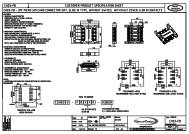
The Shielded <strong>CHAMP</strong><br />
Connector<br />
Back-to-Back Cable Connector<br />
Kit is currently available<br />
in a true 24-position<br />
IEEE-488 configuration.<br />
The IEEE-488 Kit consists<br />
of a 24-position back-toback<br />
connector assembly,<br />
a plug shield, a receptacle<br />
shield and two jackscrews.<br />
By ordering different dash<br />
numbers of the ferrule, you<br />
may obtain the appropriate<br />
diameter inner ferrule to<br />
accommodate the particular<br />
size cable to be<br />
terminated.<br />
A two-piece, snap-on strain<br />
relief cover kit is also available<br />
for those who do not<br />
wish to post mold the terminated<br />
assembly.<br />
Wire termination of the<br />
back-to-back (plug-toreceptacle)<br />
connector<br />
assembly is facilitated by<br />
the unique, one-piece insulation<br />
displacement contact<br />
design. Applicator tooling is<br />
specifically designed to<br />
mass terminate unstripped<br />
wires into their respective<br />
slotted beams. Each wire is<br />
cut to length simultaneously<br />
as termination occurs, and<br />
24 wires are terminated at<br />
the same time. See pages<br />
128 thru 131 for application<br />
tooling.<br />
The two precision-stamped<br />
shields are then assembled<br />
over the terminated connector<br />
assembly. The spring fingers<br />
of these shield halves<br />
captivate and reliably maintain<br />
contact with the braid of<br />
the cable, previously positioned<br />
over the inner ferrule<br />
prior to connector assembly<br />
termination.<br />
The spring fingers allow the<br />
shields to accept a cable<br />
range of .300 to .450 [7.62<br />
to 11.43] in diameter, and<br />
due to their stored energy<br />
design, provide continuity<br />
of shield to braid regardless<br />
of temperature, shock,<br />
vibration and other external<br />
influence. Installation of the<br />
black, plated metric jackscrews<br />
in accordance with<br />
IEEE-488 specifications<br />
finalize the assembly.<br />
120<br />
Catalog 1-1773441-4 Dimensions are in inches and Dimensions are shown for USA: 1-800-522-6752 South America: 55-11-3611-1514<br />
Issued 10-05 millimeters unless otherwise reference purposes only. Canada: 1-905-470-4425 Hong Kong: 852-2735-1628<br />
specified. Values in brackets Specifications subject Mexico: 01-800-733-8926 Japan: 81-44-844-8013<br />
www.tycoelectronics.com are metric equivalents. to change. C. America: 52-55-5-729-0425 UK: 44-141-810-8967