CHAMP Interconnection System
CHAMP Interconnection System
CHAMP Interconnection System

You also want an ePaper? Increase the reach of your titles
YUMPU automatically turns print PDFs into web optimized ePapers that Google loves.
<strong>CHAMP</strong> <strong>Interconnection</strong> <strong>System</strong><br />
<strong>CHAMP</strong> IDC Connectors (Continued)<br />
The Insulation Displacement<br />
Concept<br />
The process of terminating<br />
unstripped wires and cable<br />
by using insulation displacement<br />
technology was<br />
developed for the telephone<br />
industry over two<br />
decades ago. However,<br />
Tyco Electronics was one of<br />
the first manufacturers to<br />
recognize, research, and<br />
produce slotted beam terminations<br />
for widespread<br />
commercial use. The 50-<br />
position <strong>CHAMP</strong> connector<br />
was a creditable forerunner<br />
in this reliable technique<br />
which is used for both discrete<br />
and mass terminations.<br />
Illustration shows how<br />
the system works. As an<br />
unstripped insulated wire is<br />
forced into a slot which is<br />
narrower than the conductor<br />
diameter, the following<br />
phenomena occur:<br />
1. Insulation is displaced<br />
from the sides of the conductor.<br />
2. As the wire is pushed<br />
deeper into the slot, the<br />
bared conductor is<br />
deformed by the sides of<br />
the slot. This wiping interaction<br />
creates a clean metalto-metal<br />
union.<br />
3. The sides of the slot<br />
deflect to a final wire/slot<br />
dimension, like a spring<br />
member, and bear against<br />
the wire with a residual<br />
force that maintains high<br />
contact pressure during the<br />
life of the termination.<br />
<strong>CHAMP</strong> Connector and Terminal Identification<br />
Slotted terminals in <strong>CHAMP</strong> connector systems will accept<br />
solid or stranded (7 strands, maximum) copper conductors<br />
within 22 to 28 AWG range. Note that contact slots are<br />
designed with carefully-calibrated dimensions and accept<br />
a specific wire range and insulation diameter. The following<br />
chart shows how color-coded housings (center dot on wire<br />
side) and letter-coded terminals (stamped on outside slot)<br />
work in tandem for proper wire selection and terminations:<br />
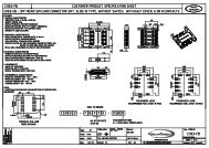
<strong>CHAMP</strong> .085 Centerline<br />
Miniature Ribbon Connector <strong>System</strong>s<br />
3<br />
Plug<br />
(Male)<br />
Receptacle<br />
(Female)<br />
Terminal Materials and<br />
Performance<br />
All slotted terminals in<br />
<strong>CHAMP</strong> connector systems<br />
are precision formed from<br />
high-strength copper alloy,<br />
and are selectively plated<br />
by a technique called<br />
AccuPlate plating process.<br />
This highly advanced<br />
method provides 30<br />
microinches minimum gold<br />
plating over 50 microinches<br />
minimum of nickel underplate<br />
on contact areas, and<br />
nickel plating (noted for its<br />
proven wear characteristics)<br />
on ramp or wear area.<br />
Durability rating for mating/<br />
unmating is 200 cycles,<br />
minimum.<br />
Note: The <strong>CHAMP</strong> connector contacts are current-rated at up to three and<br />
one half amperes. Exceptions are <strong>CHAMP</strong> Latch contacts, rated at one<br />
ampere. Keep in mind, however, that indicated current ratings do not necessarily<br />
mean that all contacts in a connector can be operated simultaneously<br />
at full-rated current. Variables must be considered, such as: connector size,<br />
contact density and material, wire size and type, ambient temperature, and<br />
PC board design (in cable-to-board applications). Consult connector product<br />
specifications for contact ratings.<br />
Color<br />
Letter<br />
Code Code Wire Range Ins.Dia.*<br />
(HSG.) (Contact) (AWG) (Max.In.)<br />
Red A One No. 24 Solid 045<br />
(Use B Slot) [1.14]<br />
Blue B One No. 24-26 .045<br />
Solid or 24 Stranded [1.14]<br />
Green C One No. 22 .045<br />
Solid or Stranded [1.14]<br />
Yellow E One No. 26, 27, .045<br />
or 28 Stranded [1.14]<br />
Orange H Two No. 26 Solid... .034<br />
Each Wire [0.86]<br />
Pink J Two No. 24 Solid... .034<br />
Each Wire [0.86]<br />
Brown F One No. 22 .056<br />
Solid or Stranded [1.42]<br />
White K No. 24-26 .056<br />
Solid or Stranded [1.42]<br />
(F Slot)<br />
* Depends upon type of insulation and applicator tool.<br />
Catalog 1-1773441-4 Dimensions are in inches and Dimensions are shown for USA: 1-800-522-6752 South America: 55-11-3611-1514<br />
Issued 10-05 millimeters unless otherwise reference purposes only. Canada: 1-905-470-4425 Hong Kong: 852-2735-1628<br />
specified. Values in brackets Specifications subject Mexico: 01-800-733-8926 Japan: 81-44-844-8013<br />
www.tycoelectronics.com are metric equivalents. to change. C. America: 52-55-5-729-0425 UK: 44-141-810-8967<br />
89