Download - Buderus
Download - Buderus
Download - Buderus

You also want an ePaper? Increase the reach of your titles
YUMPU automatically turns print PDFs into web optimized ePapers that Google loves.
Installation instructions<br />
Condensing gas boiler<br />
CAUTION!<br />
Before putting the boiler into operation read this manual carefully.<br />
WARNING!<br />
Improper installation, adjustment, alteration, service or maintenance can<br />
cause injury, loss of life or property damage. Refer to this manual. For<br />
assistance or additional information consult a qualified installer, service<br />
agency or the gas supplier.<br />
CAUTION!<br />
The operating manual is part of the documentation that is delivered to the<br />
installation's operator. Go through the information in this manual with the<br />
owner/operator and make sure that he or she is familiar with all the necessary<br />
operating instructions.<br />
NOTICE!<br />
In the Commonwealth of Massachusetts this boiler must be installed by a<br />
licensed Plumber or Gas Fitter.<br />
Warning: If the information in these instructions is not<br />
followed exactly, a fire or explosion may result causing<br />
property damage, personal injury or loss of life.<br />
– Do not store or use gasoline or other flammable vapors and liquids in<br />
the vicinity of this or any other boiler.<br />
– What to do if you smell gas<br />
• Do not try to light any boiler.<br />
• Do not touch any electrical switch; do not use any phone in your<br />
building.<br />
• Immediately call your gas supplier from a neighbor’s phone. Follow<br />
the gas supplier’s instructions.<br />
• If you cannot reach your gas supplier, call the fire department.<br />
– Installation and service must be performed by a qualified<br />
installer, service agency or the gas supplier.<br />
7215 0200 (11/2012) US/CA<br />
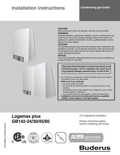
Logamax plus<br />
GB142-24/30/45/60<br />
For registered installers<br />
Please read thoroughly<br />
before installing servicing
Preface<br />
About these instructions<br />
These Installation Instructions contain important information<br />
for the safe and professional installation, start-up and<br />
maintenance of the boiler with boiler capacities 24, 30, 45<br />
and 60 kW.<br />
These Installation Instructions are intended for professional<br />
installers, who have the necessary training and<br />
experience for working on heating and gas systems.<br />
Subject to technical changes!<br />
Slight changes may be made to the illustrations, process<br />
steps and technical data as a result of our policy of<br />
continuous improvement.<br />
Updating of documentation<br />
Please contact us if you have any suggestions for<br />
improvements or corrections.<br />
2<br />
Logamax plus GB142-24/30/45/60 - We reserve the right to make any changes due to technical modifications!
Contents<br />
1 Safety and general instructions 5<br />
1.1 Designated use 5<br />
1.2 Hazard definitions 5<br />
1.3 The following instructions must be observed 5<br />
1.4 Observe these instructions for space heating<br />
water 6<br />
1.5 Tools, materials and additional equipment 6<br />
1.6 Disposal 6<br />
2 Regulations and guidelines 7<br />
3 Product description 9<br />
4 Dimensions and connections 10<br />
5 Packaging and transportation 12<br />
5.1 Scope of delivery 12<br />
5.2 Transporting the boiler 12<br />
8.13 Testing the Ignition Safety shut off device 38<br />
8.14 Installing the casing 38<br />
8.15 Informing the owner, handing over the technical<br />
documents 38<br />
9 BC10 basic controller 39<br />
9.1 Operating the BC10 basic controller 39<br />
9.1.1 Switching the heating system on and off 39<br />
9.1.2 Displaying the operating conditions of the burner<br />
and resetting the burner or resetting burner<br />
faults 39<br />
9.1.3 Displaying the heating system status and/or<br />
faults 40<br />
9.2 Carrying out additional tasks 42<br />
9.2.1 Carrying out a flue gas test 42<br />
9.2.2 Selecting partial load operation (e. g. during<br />
flue gas testing) 42<br />
9.2.3 Switching the heating system to manual mode 42<br />
9.3 Configuring the boiler 43<br />
9.3.1 Adjusting the heating capacity 43<br />
9.3.2 Setting the DHW temperature value 44<br />
9.3.3 Entering the space heating water temperature 44<br />
9.3.4 Setting the pump post-purge period 45<br />
6 Installation 13<br />
6.1 Requirements for the installation room 13<br />
6.2 Fitting the boiler 13<br />
6.3 Making the gas connection 14<br />
6.4 Fitting the heating circuit supply and return pipes 15<br />
6.5 Combustion Air and Ventilation Openings 18<br />
6.6 Installation of the flue gas adapter (included in<br />
the scope of delivery) 20<br />
6.7 Installation of the Exhaust and Air Intake system 21<br />
6.8 Conversion to Propane 26<br />
7 Electrical connections 27<br />
7.1 External connection board connections 27<br />
8 Start-up procedure 30<br />
8.1 Testing for gas leaks 31<br />
8.2 Filling the boiler 31<br />
8.3 Filling the condensate trap 32<br />
8.4 Bleeding the gas supply valve 32<br />
8.5 Checking the combustion air/flue gas connection 32<br />
8.6 Checking the orifices 33<br />
8.7 Inlet gas pressure 33<br />
8.8 Checking and adjusting the gas/air ratio 34<br />
8.9 Carrying out a leak test in operating conditions 36<br />
8.10 Measuring the carbon monoxide content (CO) 36<br />
8.11 Function testing 36<br />
8.12 Measuring the ionization current 37<br />
10 Shutting down the system 46<br />
10.1 Shut down the heating system using the<br />
control unit 46<br />
10.2 Shutting down the heating system in the event<br />
of an emergency 46<br />
11 Inspection 47<br />
11.1 Preparing the boiler for inspection 47<br />
11.2 Visual inspection for general signs of corrosion 47<br />
11.3 Internal leak testing 48<br />
11.4 Measuring the ionization current 48<br />
11.5 Measuring the inlet gas pressure 48<br />
11.6 Checking and adjusting the gas/air ratio 48<br />
11.7 Carrying out a gas leak test in operating<br />
conditions 48<br />
11.8 Measuring the carbon monoxide content (CO) 48<br />
11.9 Carrying out a pressure test of the heating<br />
system 48<br />
11.10 Checking the functioning and the safety of<br />
the air intake and flue gas conduit 48<br />
11.11 Checking venting systems 48<br />
12 Maintenance 49<br />
12.1 Cleaning the heat exchanger, burner and<br />
condensate trap 49<br />
12.2 Checking and adjusting the gas/air-ratio 51<br />
Logamax plus GB142-24/30/45/60 - We reserve the right to make any changes due to technical modifications! 3
Contents<br />
13 Appendix 52<br />
13.1 Operating messages 52<br />
13.2 Error messages 53<br />
13.3 Technical specifications 54<br />
14 Reports 56<br />
14.1 Start-up report 56<br />
14.2 Inspection report 57<br />
14.3 Maintenance report 58<br />
15 Spare parts 59<br />
16 Index 63<br />
4<br />
Logamax plus GB142-24/30/45/60 - We reserve the right to make any changes due to technical modifications!
Safety and general instructions 1<br />
1 Safety and general instructions<br />
Please observe these instructions in the interest of your<br />
own safety.<br />
1.1 Designated use<br />
The boiler was designed for heating water for a central<br />
heating system and generating domestic hot water.<br />
The boiler is delivered with a BC10 basic controller and the<br />
"Universal Automatic Burner Control Unit 3" (UBA 3)<br />
pre-installed.<br />
The boiler can be fitted with a modulating outdoor reset<br />
control AM10 (scope of delivery), a room controller RC10<br />
(optional), or an On/Off thermostat or relay panel end<br />
switch (accessories).<br />
1.2 Hazard definitions<br />
The following defined terms are used throughout the documentation<br />
to bring attention to the presence of hazards of<br />
various risk levels. Notices give important information<br />
concerning the operation of the product.<br />
DANGER:<br />
Indicates the presence of hazards that will<br />
cause severe personal injury, death or<br />
substantial property damage.<br />
WARNING:<br />
Indicates the presence of hazards that can<br />
cause severe personal injury, death or<br />
substantial property damage.<br />
CAUTION:<br />
Indicates presence of hazards that will or<br />
cause minor personal injury or property<br />
damage.<br />
CAUTION:<br />
Risk of electric shock.<br />
Indicates presence of hazards due to electric<br />
shock.<br />
NOTICE:<br />
Indicates special instructions on installation,<br />
operation or maintenance that are important<br />
but not related to personal injury or property<br />
damage.<br />
1.3 The following instructions must be<br />
observed<br />
– The boiler must only be used for its designated<br />
purpose, observing the Installation Instructions.<br />
– Only use the boiler in the combinations and with the<br />
accessories and spares listed.<br />
– Other combinations, accessories and consumables<br />
must only be used if they are specifically designed for<br />
the intended application and do not affect the system<br />
performance and the safety requirements.<br />
– Maintenance and repairs must only be carried out by<br />
trained professionals.<br />
– You must report the installation of a condensing gas<br />
boiler to the relevant gas utility company and have it<br />
approved.<br />
– You are only allowed to operate the condensing gas<br />
boiler with the combustion air/flue gas system that has<br />
been specifically designed and approved for this type of<br />
boiler.<br />
– Please note that local permission for the flue system<br />
and the condensate water connection to the public<br />
sewer system may be required.<br />
You must also observe:<br />
– the local building regulations stipulating the installation<br />
rules.<br />
– the local building regulations concerning the air intake<br />
and outlet systems and the chimney connection.<br />
– the regulations for the power supply connection.<br />
– the technical rules laid down by the gas utility company<br />
concerning the connection of the gas burner fitting to<br />
the local gas main.<br />
– the instructions and standards concerning the safety<br />
equipment for the water/space heating system.<br />
– the Installation Instructions for building heating<br />
systems.<br />
– The boiler must be located in an area where leakage of<br />
the tank or connections will not result in damage to the<br />
area adjacent to the boiler or to lower floors of the<br />
structure. When such locations cannot be avoided, it is<br />
recommended that a suitable drain pan, adequately<br />
drained, be installed under the boiler. The pan must not<br />
restrict combustion air flow.<br />
– The boiler must be installed such that the gas ignition<br />
system components are protected from water (dripping,<br />
spraying, rain etc.) during boiler operation and service.<br />
– The boiler must not be installed on carpeting.<br />
– Do not restrict or seal any air intake or outlet openings.<br />
– If you find any defects, you must inform the owner of the<br />
system of the defect and the associated hazard in<br />
writing.<br />
Logamax plus GB142-24/30/45/60 - We reserve the right to make any changes due to technical modifications! 5
1<br />
Safety and general instructions<br />
DANGER<br />
if flammable gas explodes.<br />
Beware if you smell gas: there may be an<br />
explosion hazard!<br />
Warning: If the information in these<br />
instructions is not followed exactly, a fire<br />
or explosion may result causing property<br />
damage, personal injury or death.<br />
• Do not store or use gasoline or other flammable<br />
vapors and liquids in the vicinity of<br />
this or any other boiler.<br />
What to do if you smell gas<br />
• Do not try to light any boiler.<br />
• Do not touch any electrical switch; do not<br />
use any phone in your building.<br />
• Immediately call your gas supplier from<br />
a neighbor’s phone. Follow the gas<br />
supplier’s instructions.<br />
• If you cannot reach your gas supplier, call<br />
the fire department.<br />
Installation and service must be performed by<br />
a qualified installer, service agency or the gas<br />
supplier.<br />
1.4 Observe these instructions for space<br />
heating water<br />
Unsuitable heating system water can promote the formation<br />
of scale or sludge, which affects system efficiency.<br />
It can also cause corrosion and reduce life of the heat<br />
exchanger.<br />
– You must follow <strong>Buderus</strong> guidelines for boiler water<br />
quality.<br />
– Thoroughly flush the system prior to filling.<br />
– Use of a <strong>Buderus</strong> approved boiler cleaner is<br />
recommended.<br />
– Never use salt bedding exchangers to soften the water.<br />
– Do not use inhibitors or other additives unless approved<br />
by <strong>Buderus</strong> for that purpose!<br />
– When frost protection of the heating system is desired,<br />
only use <strong>Buderus</strong>-approved Aluminum-safe antifreeze.<br />
– When using oxygen-permeable pipes, e. g. for floor<br />
heating systems, you must separate the system using<br />
heat exchangers.<br />
– The maximum permissible flow rate of the<br />
GB142-24/30 this is 11 GPM (gal./min.)(= 42 l/min.), for<br />
the GB142-45 is 15 GPM (= 57 l/min.) and for the<br />
GB142-60 is 20 GPM (= 76 l/min.).<br />
1.5 Tools, materials and additional<br />
equipment<br />
For the installation and maintenance of the boiler you will<br />
need the standard tools for space heating, gas and water<br />
fitting.<br />
In addition, a handtruck with a fastening belt is useful.<br />
1.6 Disposal<br />
– Dispose of the boiler packaging in an environmentally<br />
sound manner.<br />
– Dispose of components of the heating system (e. g.<br />
boiler or control device), that must be replaced in an<br />
environmentally responsible manner.<br />
6<br />
Logamax plus GB142-24/30/45/60 - We reserve the right to make any changes due to technical modifications!
Regulations and guidelines 2<br />
2 Regulations and guidelines<br />
The installation must conform to the requirements of the<br />
authority having jurisdiction or, in the absence of such<br />
requirements, to the latest edition of the National Fuel Gas<br />
Code, ANSI Z223.1. In Canada, installation must be in<br />
accordance with the requirements of CAN/CSA B149.1,<br />
Natural Gas and Propane Installation Code.<br />
Where required by the authority having jurisdiction, the<br />
installation must conform to the Standard for Controls and<br />
Safety Devices for Automatically Fired Boilers, ANSI/<br />
ASME CSD-1.<br />
Install CO detectors per local regulations. Boiler requires<br />
yearly maintenance, see maintenance section see<br />
chapter 12 "Maintenance", page 49.<br />
Operating Limits of the boiler:<br />
Max. boiler temperature:<br />
Max. operating pressure:<br />
230 °F (110 °C)<br />
44 psi (3 bar)<br />
The hot water distribution system must comply with all<br />
applicable codes and regulations. When replacing an<br />
existing boiler, it is important to check the condition of the<br />
entire hot water distribution system to ensure safe operation.<br />
Massachusetts Installations Only:<br />
(a) For all side wall side horizontally vented gas fueled<br />
equipment installed in every dwelling, building or structure<br />
used in whole or in part for residential purposes, including<br />
those owned or operated by the Commonwealth and<br />
where the side wall exhaust vent termination is less than<br />
seven (7) feet above finished grade in the area of the<br />
venting, including but not limited to decks and porches, the<br />
following requirements shall be satisfied:<br />
1. INSTALLATION OF CARBON MONOXIDE<br />
DETECTORS. At the time of installation of the side<br />
wall horizontal vented gas fueled equipment, the<br />
installing plumber or gasfitter shall observe that a hard<br />
wired carbon monoxide detector with an alarm and<br />
battery back-up is installed on the floor level where the<br />
gas equipment is to be installed. In addition, the<br />
installing plumber or gasfitter shall observe that a<br />
battery operated or hard wired carbon monoxide<br />
detector with an alarm is installed on each additional<br />
level of the dwelling, buiding or structure served by the<br />
side wall horizontal vented gas fueled equipment. It<br />
shall be the responsibility of the property owner to<br />
secure the services of qualified licensed proffesionals<br />
for the installation of hard wired carbon monoxide<br />
detectors.<br />
a. In the event that the side wall horizontally vented<br />
gas fueled equipment is installed in a crawl space<br />
or an attic, the hard wired carbon monoxide<br />
detector with alarm and battery back-up may be<br />
installed on the next adjacent floor level.<br />
b. In the event that the requirements of this<br />
subdivision can not be met at the time of<br />
completion of installation, the owner shall have a<br />
period of thirty (30) days to comply with the above<br />
requirements; provided, however, that during said<br />
thirty (30) day period, a battery operated carbon<br />
monoxide detector with an alarm shall be installed.<br />
2. APPROVED CARBON MONOXIDE DETECTORS.<br />
Each carbon monoxide detector as required in<br />
accordance with the above provisions shall comply<br />
with NPA 720 and be ANSI/UL 2034 listed and<br />
IAS certified.<br />
3. SIGNAGE. A metal or plastic identification plate shall<br />
be permanently mounted to the exterior of the building<br />
at a minimum height of eight (8) feet above grade<br />
directly in line with the exhaust vent terminal for the<br />
horizontally vented gas fueled heating appliance or<br />
equipment. the sign shall read, in print size no less<br />
than one-half (½) inch in size, “GAS VENT DIRECTLY<br />
BELOW. KEEP CLEAR OF ALL OBSTRUCTIONS”.<br />
4. INSPECTION. The state or local gas inspector of the<br />
side wall horizontally vented gas fueled equipment<br />
shall not approve the installation unless, upon<br />
inspections, the inspector observes carbon monoxide<br />
detectors and signage installed in accordance with the<br />
provisions of 248 CRM 5.08(2)(a)1 through 4.<br />
(b) EXEMPTIONS: The following equipment is exempt<br />
from 248 CRM 5.08(2)(a)1 through 4:<br />
1. The equipment listed in Chapter 10 entitled<br />
“Equipment Not Required To Be Vented” in the<br />
most currect edition of NFPA 54 as adopted by the<br />
board: and<br />
2. Product Approved side wall horizontally vented gas<br />
fueled equipment installed in a room or structure<br />
separate from the dwelling, building or structure<br />
used in whole or in part for residential puposes.<br />
Logamax plus GB142-24/30/45/60 - We reserve the right to make any changes due to technical modifications! 7
2<br />
Regulations and guidelines<br />
(c) MANUFACTURERS REQUIREMENTS - GAS EQUIP-<br />
MENT VENTING SYSTEM REQUIRED.<br />
When the manufacturer of Product Approved side wall horizontally<br />
mounted gas equipment provides a venting system<br />
design or venting system components with the equipment,<br />
the instructions provided by the manufacturer for the installation<br />
of the equipment and venting shall include:<br />
1. Detailed instructions for the installation of the venting<br />
system or the venting system components: and<br />
2. A complete parts list for the venting system design or<br />
venting system.<br />
(d) MANUFACTURERS REQUIREMENTS - GAS EQUIP-<br />
MENT VENTING SYSTEM NOT PROVIDED.<br />
When the manufacturer of Product Approved side wall horizontally<br />
vented gas fueled equipment does not provide the<br />
parts for the venting of flue gases, but identifies “special<br />
venting systems”, the following requirements shall be satisfied<br />
by the manufacturer:<br />
1. The referenced “special venting systems” shall be<br />
included with the appliance or equipment installation<br />
instructions: and<br />
2. The “special venting systems” shall be Product<br />
Approved by the Board, and the instructions for that<br />
system shall include a parts list and detaild<br />
installation instructions.<br />
(e) A copy of all instructions for all Product Approved side<br />
wall horizontally vented gas fueled equipment, all venting<br />
instructions, all parts lists for venting instructions, and/or<br />
venting design instructions shall remain with the appliance<br />
or equipment at the completion of the installation.<br />
8<br />
Logamax plus GB142-24/30/45/60 - We reserve the right to make any changes due to technical modifications!
Product description 3<br />
3 Product description<br />
6<br />
7<br />
8<br />
6 7<br />
9<br />
10<br />
11<br />
8<br />
5<br />
4<br />
12<br />
13<br />
5<br />
4<br />
9<br />
10<br />
11<br />
12<br />
3<br />
3<br />
2<br />
9<br />
2<br />
9<br />
1<br />
14<br />
15<br />
16<br />
Fig. 1 Logamax plus GB142-24/30 (left) and GB142-45/60 (right)<br />
pos. 1: Drawer with control unit<br />
2: Universal Burner Automat (UBA3)<br />
3: Control unit BC10<br />
4: Gas valve<br />
5: Cover<br />
6: Flue measuring points<br />
7: Parallel flue<br />
8: Burner<br />
1<br />
14<br />
15 13 16 17<br />
9: Latches of which two have locks<br />
10: Sighting glass<br />
11: Heat exchanger<br />
12: Back cover<br />
13: Air intake for the fan<br />
14: Fan<br />
15: Condensate trap and internal condensate drain flue gas pipe<br />
16: External Connection Board (under the cover)<br />
17: Pressure sensor<br />
2<br />
3 4 5 6<br />
100<br />
90<br />
110<br />
120<br />
130<br />
140<br />
90<br />
110<br />
130<br />
150<br />
170<br />
190<br />
1<br />
Fig. 2 Basic Controller Logamatic BC10<br />
pos. 1: Main switch<br />
2: DHW temperature knob 1)<br />
3: LED "DHW status"<br />
4: Display<br />
5: Space heating water temperature knob<br />
6: LED "Heating system status"<br />
12 11 10<br />
9<br />
8<br />
7: Under the cover a RC system controller can be installed<br />
8: LED "Burner Operation"<br />
9: Service Tool connector<br />
10: "Service" e button<br />
11: "Chimney sweep" d button<br />
12: "Reset" c button<br />
1) ECO mode means that the temperature inside the hot water tank is 140 °F (60 °C), with a hysteresis (T) of 18 °F (10 °C) instead of 9 °F (5 °C)<br />
7<br />
Logamax plus GB142-24/30/45/60 - We reserve the right to make any changes due to technical modifications! 9
4<br />
Dimensions and connections<br />
4 Dimensions and connections<br />
20" (500 mm)<br />
4" (100 mm)<br />
6.2"<br />
(158 mm)<br />
5.5" (239 mm)<br />
22" (560 mm)<br />
13.2" (335 mm) 4.3" (110 mm)<br />
A<br />
B<br />
12" (300 mm)<br />
0.25"<br />
(6 mm)<br />
28" (712 mm)<br />
1.2" (30 mm) 7.5" (190 mm)<br />
3" (75 mm)<br />
C<br />
16" (420 mm)<br />
D E F G<br />
1.8" (46 mm)<br />
18.7" (475 mm)<br />
2.2" (55 mm)<br />
3" (75 mm)<br />
6" (150 mm)<br />
6" (150 mm)<br />
3" (75 mm)<br />
> 6"<br />
(150 mm)<br />
> 4"<br />
(100 mm)<br />
Fig. 3 Dimensions and connections for boiler GB142-24/30 (dimensions in inches)<br />
AA (A) = Flue gas connection (inside diameter 3'')<br />
LA (B) = Air intake (inside diameter 3'')<br />
AKO (E) =<br />
GAS (D) =<br />
Condensate water outlet, Ø 1.3” (Ø 32 mm) outside<br />
diameter<br />
Gas connection, ¾” NPT<br />
RK (G)<br />
VK (F)<br />
WB (C)<br />
=<br />
=<br />
=<br />
Return, Ø 1.0” 1 (Ø 25.4 mm)<br />
Supply, Ø 1.0” 1 (Ø 25.4 mm)<br />
Wall bracket<br />
1 One Ø 1.0” (Ø 25.4 mm) inside x 1'' NPT threaded compression fitting is delivered enclosed with boiler packaging<br />
NOTICE<br />
Observe the lateral minimum distances of the<br />
boiler (12” = 300 mm) and the necessary<br />
distances (24” (600 mm) at the front and<br />
4” (100 mm) at the top) for removing the casing<br />
and for servicing.<br />
Closet clearances are:<br />
4” (100 mm) to the right, 4” (100 mm) at the top<br />
and 6” (150 mm) to the left.<br />
10<br />
Logamax plus GB142-24/30/45/60 - We reserve the right to make any changes due to technical modifications!
Dimensions and connections 4<br />
20" (500 mm)<br />
12" (300 mm)<br />
4" (100 mm)<br />
6.2"<br />
(158 mm)<br />
0.25"<br />
(6 mm)<br />
5.5" (239 mm)<br />
28" (712 mm)<br />
1.2" (30 mm) 7.5" (190 mm)<br />
35.4" (900 mm)<br />
13.2" (335 mm) 4.3" (110 mm)<br />
A<br />
B<br />
9.7" (246 mm)<br />
C<br />
16" (420 mm)<br />
D E F G<br />
1.8" (46 mm)<br />
18.7" (475 mm)<br />
2.2" (55 mm)<br />
3" (75 mm)<br />
20.7" (526 mm)<br />
3" (75 mm)<br />
> 6"<br />
(150 mm)<br />
> 4"<br />
(100 mm)<br />
Fig. 4 Dimensions and connections for boiler GB142-45/60 (dimensions in inches)<br />
AA (A) = Combustion air<br />
LA (B) = Air intake<br />
AKO (E) =<br />
GAS (D) =<br />
Condensate water outlet, Ø 1.3” (Ø 32 mm)<br />
Gas connection, ¾” NPT<br />
RK (G)<br />
VK (F)<br />
WB (C)<br />
=<br />
=<br />
=<br />
Return, Ø 1.0” 1 (Ø 25.4 mm)<br />
Supply, Ø 1.0” 1 (Ø 25.4 mm)<br />
Wall bracket<br />
1 One Ø 1.0” (Ø 25.4 mm) inside x 1'' NPT threaded compression fitting is delivered enclosed.<br />
NOTICE<br />
Observe the lateral minimum distances of the<br />
boiler (12” = 300 mm) and the necessary<br />
distances (24” (600 mm) at the front and<br />
4” (100 mm) at the top) for removing the casing<br />
and for servicing.<br />
Closet clearances are:<br />
4” (100 mm) to the right, 4” (100 mm) at the top<br />
and 6” (150 mm) to the left.<br />
Logamax plus GB142-24/30/45/60 - We reserve the right to make any changes due to technical modifications! 11
5<br />
Packaging and transportation<br />
5 Packaging and transportation<br />
5.1 Scope of delivery<br />
The boiler is delivered fully assembled.<br />
• When receiving the delivery, check if the packaging is<br />
intact.<br />
• Check that all the items listed in see table 1 are included<br />
in the delivery.<br />
5.2 Transporting the boiler<br />
1<br />
9<br />
3<br />
2<br />
4<br />
CAUTION<br />
The boiler may be damaged when it is improperly<br />
secured.<br />
– Only transport the boiler using the right<br />
transportation equipment, such as a<br />
handtruck with a fastening belt or special<br />
equipment for manoeuvering steps.<br />
– During transportation the boiler must be<br />
secured on the transportation equipment to<br />
prevent it from falling off.<br />
– Protect all parts against impacts if they are to<br />
be transported.<br />
– Observe the transportation markings on the<br />
packaging.<br />
• Packaged boilers must always be lifted and carried to<br />
their destination by two people, or you must use a<br />
handtruck or special equipment to transport them to their<br />
destination.<br />
• Transport the boiler to the room where it is to be installed.<br />
Fig. 5<br />
8<br />
Pos. Parts<br />
Items supplied with unit<br />
Quantity Packaging<br />
1 Boiler with casing 1 1 box<br />
2 Wall bracket 1<br />
3 Technical documents 1<br />
including:<br />
- User's Instructions<br />
- Installation Instructions<br />
- wall mounting template<br />
- Servicing Instructions<br />
3<br />
4 Compression fittings 2<br />
5 AM10 with outdoor sensor 1<br />
6 Flue gas adapter 1<br />
7 Propane conversion kit 1<br />
8 Boiler connection kit,<br />
including the DHW sensor<br />
9 GB142 Boiler manifold<br />
including:<br />
- low loss header<br />
- pressure relief valve<br />
- tridicator<br />
- DHW connections<br />
- Grundfos 15-58 3-speed<br />
boiler circulator<br />
- supply and return shutoff ball<br />
valves<br />
Table 1<br />
6<br />
Items supplied with unit<br />
1 The user’s instructions (in a special format) is located in the boiler<br />
drawer<br />
5<br />
1<br />
1<br />
7<br />
12<br />
Logamax plus GB142-24/30/45/60 - We reserve the right to make any changes due to technical modifications!
Installation 6<br />
6 Installation<br />
6.1 Requirements for the installation room<br />
DANGER<br />
– Install the heating system in a frost-free<br />
room.<br />
– Do not store any flammable materials or<br />
liquids in the immediate vicinity of the boiler.<br />
– Never use any chlorinated detergents or<br />
halogenated hydrocarbons (e. g. in<br />
spraycans, solvents and detergents, paints,<br />
adhesives).<br />
– Do not allow too much dust to collect on the<br />
boiler.<br />
6.2 Fitting the boiler<br />
Observe the installation clearances of the combustion air/<br />
flue gas system.<br />
NOTICE<br />
– To protect the connection orifice you must<br />
not remove the styrofoam bottom panel.<br />
– Do not lift the boiler by the drawer.<br />
– Do not remove the transport safety clamps<br />
(see fig. 6) from the drawer at this time.<br />
– Protect the boiler and the combustion<br />
air/flue gas orifice against pollution during<br />
installation.<br />
• Remove the packaging materials and dispose of them.<br />
• Use the mounting template to mark the drill holes.<br />
• Install the wall bracket taking into account the necessary<br />
service clearances.<br />
• Remove the transport safety clamps (fig. 6).<br />
Fig. 6<br />
Removing the transport safety clamps<br />
Logamax plus GB142-24/30/45/60 - We reserve the right to make any changes due to technical modifications! 13
6<br />
Installation<br />
• Use the radiator key to unlock the two latches a quarter<br />
turn (fig. 7, pos. 1).<br />
• Open the latches (fig. 7, pos. 2).<br />
• Remove the casing by lifting it upwards and then pulling<br />
it forwards (fig. 7, pos. 3); do not hold the casing by the<br />
latches.<br />
• Hold the boiler by the rear boiler casing and place it on<br />
the wall bracket.<br />
3<br />
2<br />
2<br />
1<br />
• Level out the boiler.<br />
2<br />
2<br />
Fig. 7<br />
Removing the casing<br />
6.3 Making the gas connection<br />
DANGER<br />
Only carry out work on gas lines if you are<br />
licensed for such work.<br />
• Determine proper size gas pipe for the installation using<br />
see table 2 and see table 3. Do not forget the pipe fitting<br />
losses and observe proper size of the fittings.<br />
• Install the furnished ¾” gas cock on the gas connection.<br />
• Connect the gas pipe to the gas cock (fig. 8, pos. 1) so<br />
that it is free from any strain.<br />
1<br />
Fig. 8<br />
Making the gas connection<br />
NOTICE<br />
When installing the gas supply connection, it<br />
must comply with local regulations or, if such<br />
regulations do not exist, with the National Fuel<br />
Gas Code, ANSI Z 223.1.<br />
In Canada, the gas supply connection must<br />
comply with local regulations or, if such regulations<br />
do not exist, with CAN/CSA B149.1,<br />
Natural Gas and Propane Installation Code.<br />
A sediment trap must be provided upstream of the gas<br />
controls.<br />
Length of<br />
pipe (feet)<br />
Gas Volume Capacity<br />
(ft 3 / hr) 1<br />
¾" 1" 1 ¼" 1 ½"<br />
10 278 520 1,060 1,600<br />
20 190 350 730 1,100<br />
30 152 285 590 890<br />
40 130 245 500 760<br />
50 115 215 440 670<br />
75 93 175 360 545<br />
100 79 160 305 480<br />
150 64 120 250 380<br />
Table 2 Gas Pipe Capacity for different pipe sizes<br />
1 Maximum pipe capacity in ft 3 /hr, based on a specific gravity of<br />
.60 (42 mbar) and a inlet gas pressure of 14 inches W.C.<br />
(35 mbar) or less and a pressure drop of .3 inches W.C. (20 mbar)<br />
14<br />
Logamax plus GB142-24/30/45/60 - We reserve the right to make any changes due to technical modifications!
Installation 6<br />
Steel pipe Equivalent length for Pipe Fittings in feet<br />
diameter<br />
Type of pipe fitting<br />
in inches<br />
90°-Elbow Tee Gate valve Gas cocks<br />
(flow thru<br />
branch)<br />
Equivalent length in feet<br />
¾ 2.1 4.1 0.5 1.25<br />
1 2.6 5.2 0.6 1.60<br />
1 ¼ 3.5 6.9 0.8 2.15<br />
1 ½ 4.0 8.0 0.9 2.50<br />
Table 3<br />
Equivalent length for pipe fittings in feet<br />
6.4 Fitting the heating circuit supply and<br />
return pipes<br />
NOTICE<br />
– To protect the entire heating system we<br />
require installing a WYE strainer in the return<br />
circuit. When retrofitting the boiler to an<br />
existing heating system this filter is required.<br />
– Install shut-off valves immediately before and<br />
after the dirt particle filter to allow the filter to<br />
be cleaned.<br />
• Fit a filling and drain cock in the heating system supply<br />
pipe if required.<br />
• Also fit an adequately sized safety valve in the system<br />
that meets all applicable codes and regulations.<br />
NOTICE<br />
When using oxygen-permeable pipes, e. g. for<br />
radiant floor heating systems, you must separate<br />
the system using heat exchangers.<br />
<strong>Buderus</strong> recommends hydraulically isolating<br />
snowmelt systems using heat exchangers.<br />
• Thoroughly flush all pipes and radiators. Use of a<br />
<strong>Buderus</strong> approved boiler cleaner is recommended.<br />
• Refer to the installation template for the pipe connection<br />
dimensions.<br />
• Fit the compression fittings (fig. 9, pos. 1 and 2) first to<br />
the Hydronic set (see fig. 10, 11 and 12) and then to the<br />
boiler.<br />
• Connect the expansion tank to the system.<br />
• Connect the pipes so that they are free from strain.<br />
Connecting boiler with DHW tank<br />
• Connect the external hot-water tank according to the<br />
Installation instructions of the hot-water tank and fittings<br />
concerned.<br />
1 2<br />
11<br />
11<br />
3<br />
5<br />
8<br />
9<br />
Fig. 9 Pump manifold installation<br />
pos. 1: Compression fitting (heating system supply pipe)<br />
2: Compression fitting (heating system return pipe)<br />
3: Relief valve<br />
4: DHW return 1“FPT<br />
5: DHW supply 1“FPT<br />
6: Low loss header<br />
7: System return 1½ MPT<br />
8: Drain valve<br />
9: System supply 1½ MPT<br />
10: Tridicator<br />
11: Di electric union<br />
4<br />
6<br />
10<br />
7<br />
Logamax plus GB142-24/30/45/60 - We reserve the right to make any changes due to technical modifications! 15
6<br />
Installation<br />
Piping examples<br />
The following illustrations are two Installation examples.<br />
NOTICE<br />
The following illustrations are simplified conceptual<br />
illustrations only.<br />
Piping and field components must be field verified.<br />
FLUE GAS<br />
GB142<br />
AIR INTAKE<br />
• A hot water boiler installed above radiation level or as<br />
required by the Authority having jurisdiction, must be<br />
provided with a low water cutoff device either as a part of<br />
the boiler or at the time of boiler installation.<br />
Fig. 10 is a schematic representation of fig. 9.<br />
NOTICE<br />
If this boiler is installed in a closed water supply<br />
system with an external indirect DHW tank,<br />
such as one having a backflow preventer in the<br />
cold water supply line, means shall be provided<br />
to control thermal expansion. Contact the water<br />
supplier or local plumbing inspector on how to<br />
control this situation.<br />
Relief valve<br />
The indirect DHW tank must have a temperature<br />
and pressure relief valve installed. The<br />
relief valve shall comply with the Standard for<br />
Relief Valves and Automatic Gas Shutoff<br />
Devices for Hot Water Supply Systems, ANSI<br />
Z21.22-CSA 4.4.<br />
• Install the relief valve according fig. 10.<br />
The relief valve must comply with following<br />
specifications:<br />
– dimensions: height 2¼ inch (57.15 mm),<br />
width 2 inch (50.8 mm).<br />
– 30 Psi (2 bar) discharge pressure.<br />
– discharge is ¾ inch (19.1 mm) female in<br />
diameter.<br />
1<br />
3<br />
5<br />
7<br />
Fig. 10 Schematic representation of the boiler with the hydronic set<br />
pos. 1: DHW supply 1“FPT<br />
2: DHW return 1“FPT<br />
3: pump manifold shut-off valve<br />
4: Low loss header<br />
5: drain valve<br />
6: PT gauge (pressure and temperature gauge)<br />
7: System supply 1½ MPT<br />
8: System return 1½ MPT<br />
PT<br />
pump manifold<br />
2<br />
4<br />
6<br />
8<br />
16<br />
Logamax plus GB142-24/30/45/60 - We reserve the right to make any changes due to technical modifications!
Installation 6<br />
WARNING<br />
FLUE GAS<br />
AIR INTAKE<br />
No valve is to be placed between the relief valve<br />
and the tank. Discharge of the relief valve must<br />
be conducted to a suitable place for disposal<br />
when relief occurs and no reducing coupling or<br />
other restriction may be installed in the<br />
discharge line.<br />
NOTICE<br />
For the maximum permissible flow rate of the<br />
DHW pump see §1.4 (page 6)<br />
1<br />
3<br />
GB142<br />
5<br />
7 PT<br />
9<br />
Optional Additional<br />
DHW<br />
Tank<br />
Tank<br />
2<br />
4<br />
6<br />
10<br />
zones<br />
Aditional zones<br />
Radiant<br />
8<br />
Fig. 11<br />
Schematic representation of the boiler with the hydraulic set<br />
connected to an optional hot water tank with one or multiple<br />
zones including one pump and zone valves<br />
1: pressure relief valve<br />
2: primary pump<br />
3: DHW pump<br />
4: Shut-off valve<br />
5: Low los header<br />
6: PT gauge (pressure and<br />
temperature gauge)<br />
7: drain valve<br />
8: zone valve<br />
9: secondary pump<br />
10: shut-off valve<br />
NOTICE<br />
Primary boiler pump must have an internal<br />
check valve.<br />
FLUE GAS<br />
GB142<br />
AIR INTAKE<br />
1<br />
3<br />
5<br />
7 PT<br />
Optional Additional<br />
DHW<br />
Tank<br />
Tank<br />
2<br />
4<br />
6<br />
9<br />
zones<br />
Aditional zones<br />
Radiant<br />
8<br />
Fig. 12<br />
Schematic representation of the boiler with the<br />
Hydronic set connected to an optional hot water tank<br />
with one or multiple zones and zone pumps<br />
1: pressure relief valve<br />
2: primary pump<br />
3: DHW pump<br />
4: shut-off valve<br />
5: Low loss header<br />
6: PT gauge (pressure and<br />
temperature gauge)<br />
7: drain valve<br />
8: zone pump<br />
9: shut-off valve<br />
Logamax plus GB142-24/30/45/60 - We reserve the right to make any changes due to technical modifications! 17
6<br />
Installation<br />
6.5 Combustion Air and Ventilation<br />
Openings<br />
Provisions for combustion and ventilation air must be made<br />
in accordance with section 5.3, Air for Combustion and<br />
Ventilation, of the National Flue Gas Code, ANSI Z223.1, or<br />
Sections 7.2, 7.3 or 7.4 of CAN/CGA B149, Installation<br />
Codes, or applicable provisions of the local building codes.<br />
CAUTION:<br />
BOILER DAMAGE AND OPERATIONAL<br />
FAILURES !<br />
Due to insufficient or lacking openings for<br />
combustion air and/or ventilation of the boiler<br />
room.<br />
Provisions for combustion air and ventilation are<br />
always required, regardless whether the<br />
combustion air is taken from the outside (sealed<br />
combustion) or inside (non sealed combustion<br />
for combustion).<br />
Insufficient ventilation of the boiler room can<br />
lead to high air temperatures. This can result in<br />
boiler damage.<br />
– Make sure that intake and exhaust openings<br />
are sufficiently sized and no reduction or<br />
closure of openings takes place.<br />
– When the problem is not resolved, do not<br />
operate the boiler.<br />
– Please note these restrictions and its<br />
dangers to the operator of the boiler.<br />
WARNING:<br />
BOILER DAMAGE !<br />
due to contaminated air.<br />
– Boiler must be clear and free from<br />
combustible materials, gasoline and other<br />
flammable vapors and liquids, and corrosive<br />
liquids and vapors.<br />
Never use chlorine and hydrocarbon<br />
containing chemicals (such as spray<br />
chemicals, solution and cleaning agents,<br />
paints, glues etc) in the vicinity of the boiler.<br />
– Do not store and use these chemicals in the<br />
boiler room.<br />
– Avoid excessive dust formation and build-up.<br />
NOTICE<br />
When one expects contaminated combustion<br />
air (near swimming pools, chemical cleaning<br />
operations and hair salons), sealed combustion<br />
operation is recommended.<br />
18<br />
Logamax plus GB142-24/30/45/60 - We reserve the right to make any changes due to technical modifications!
Installation 6<br />
DANGER:<br />
FIRE DANGER !<br />
due to flammable materials or liquids.<br />
– Do not store flammable materials and liquids<br />
in the immediate vicinity of the boiler.<br />
All Air from Inside the Building (non sealed combustion)<br />
The closet shall be provided with two permanent openings<br />
communicating directly with an additional room(s). The total<br />
input of all gas utilization equipment installed in the<br />
combined space shall be considered in making this determination.<br />
Each opening shall have a minimum free area of<br />
1 square inch per 1,000 Btu per hour of total input rating of<br />
all gas utilization equipment in the confined space, but no<br />
less than 100 square inches. One opening shall commence<br />
within 12 inches (305 mm) of the top, and one opening shall<br />
commence within 12 inches (305 mm) of the bottom of the<br />
enclosure. The minimum dimension of air openings shall be<br />
not less than 3 inches (75 mm).<br />
1. Where directly communicating with the outdoors, each<br />
opening shall have a minimum free area of 1 square<br />
inch per 4,000 Btu/hr of total input rating of all<br />
equipment in the enclosure.<br />
2. Where communicating with the outdoors through<br />
vertical ducts, each opening shall have a minimum free<br />
area of 1 square inch per 4,000 Btu/hr of total input<br />
rating of all equipment in the enclosure.<br />
3. Where communicating with the outdoors through<br />
horizontal ducts, each opening shall have a minimum<br />
free area of 1 square inch per 2,000 Btu/hr of total input<br />
rating of all equipment in the enclosure.<br />
4. Where ducts are used, they shall be of the same crosssectional<br />
area as the free area of the opening to which<br />
they connect.<br />
Logamax plus GB142-24/30/45/60 - We reserve the right to make any changes due to technical modifications! 19
6<br />
Installation<br />
6.6 Installation of the flue gas adapter<br />
(included in the scope of delivery)<br />
Before installing the exhaust and air intake system, it is<br />
necessary to remove the transport safety device and to<br />
install the flue gas adapter.<br />
NOTICE<br />
The transport safety device has been installed<br />
to prevent unwanted movement of the heat<br />
exchanger during transport.<br />
• Remove the transport safety device with the two screws<br />
(see fig. 13).<br />
Fig. 13<br />
Removing the transport safety device<br />
• Remove the protective cap from the internal condens<br />
bypass pipe. Place the flue gas adapter and connect the<br />
internal condens bypass pipe (see fig. 14).<br />
Fig. 14<br />
Placing the flue gas adapter<br />
• Screw on the flue gas adapter using six screws (see<br />
fig. 15).<br />
Fig. 15<br />
Connecting the flue gas adapter<br />
20<br />
Logamax plus GB142-24/30/45/60 - We reserve the right to make any changes due to technical modifications!
Installation 6<br />
6.7 Installation of the Exhaust and Air Intake<br />
system<br />
NOTICE<br />
Consult local and state codes pertaining to<br />
special building code and fire department<br />
requirements. Adhere to national code requirements.<br />
NOTICE<br />
Observe the listed maximum lengths of vent<br />
system, which are boiler model dependent. The<br />
maximum permissible lengths are listed in see<br />
table 4, page 26.<br />
An optional concentric vent/air intake body (see fig. 19 and<br />
27) can be used for the installation of a vertical venting<br />
system as well as for a horizontal venting system.<br />
The concentric vent/air intake body can be ordered by<br />
<strong>Buderus</strong> Hydronic Systems, part no. BRYKGAVTO601CV.<br />
Other optional vent kits are:<br />
383-500-397 Plastic Vent Kit<br />
The boiler can also be operated with separate air intake and<br />
exhaust piping (see fig. 20 and fig. 27).<br />
The termination shall be at least 4 ft (1,220 mm) for the U.S.<br />
and 6 ft (1,830 mm) for Canada away from a gas utility<br />
gauge, service regulator or the like (for non sealed combustion<br />
applications only).<br />
The termination shall terminate at least 4 ft (1,220 mm)<br />
below, 4 ft (1,220 mm) horizontally from, or 1 ft (305 mm)<br />
above any door, window, or gravity air inlet into any building.<br />
Vent must be at least 12 inches (305 mm) above grade,<br />
anticipated snow line or roof surface (Canada 18” (457 mm)<br />
minimum) (see fig. 17).<br />
Vent termination must be at least 7 ft (2,135 mm) above<br />
a public walkway (see fig. 18).<br />
Vent must be 3 ft (915 mm)above any forced air intake<br />
within 10 ft (3,050 mm) (see fig. 18).<br />
Do not extend exposed vent pipe outside the building<br />
beyond recommended distance. Condensate could freeze<br />
and block vent pipe.<br />
Vent should terminate at least 3 ft (915 mm) away from adjacent<br />
outside walls, inside corners and 5ft (1525 mm) below<br />
roof overhang (see fig. 18).<br />
It is not recommended to terminate vent above any door or<br />
window, condensate can freeze causing ice formations.<br />
Do not use chimney as a raceway if another boiler or fireplace<br />
is vented into or through chimney.<br />
Logamax plus GB142-24/30/45/60 - We reserve the right to make any changes due to technical modifications! 21
6<br />
Installation<br />
All vent pipes must be glued, except for the flue gas adapter<br />
(fig. 16, pos. 1) which is screwed into place and the first<br />
connection to the flue gas adapter (fig. 16, pos. 2). Installed<br />
you can slide the pipe onto the adapter, properly supported<br />
and the exhaust pipe must be pitched a minimum of a ¼inch<br />
per foot back to the boiler. This allows the condensate to<br />
drain away. Fix the screws (fig. 16, pos. 3), this is obliged for<br />
Canada.<br />
All combustion air and vent pipe materials and fittings must<br />
comply with the following:<br />
Item Material United states Canada<br />
PVC<br />
schedule 40<br />
ANSI/ASTM D1785<br />
2<br />
3<br />
1<br />
Vent or air<br />
pipe and<br />
fitting<br />
Pipe cement/<br />
primer<br />
PVC-DWV<br />
CPVC<br />
schedule 40<br />
ABS-DWV<br />
schedule 40<br />
PVC<br />
CPVC<br />
ABS<br />
ANSI/ASTM D2665<br />
ANSI/ASTM F441<br />
ANSI/ASTM D2661<br />
ANSI/ASTM D2564<br />
ANSI/ASTM F493<br />
ANSI/ASTM D2235<br />
CSA or BH<br />
Gas venting<br />
systems,<br />
ULC S636 *<br />
certified only<br />
Fig. 16<br />
Vent pipes<br />
* Components of the certified vent systems must not be interchanged<br />
with other vent systems or unlisted pipe fittings Plastic components,<br />
and specified primers and glues of the certified vent system must be<br />
from a single system manufacturer and not intermixed with other system<br />
manufacturer's vent system parts.<br />
NOTICE<br />
Do not use cellular core pipe.<br />
NOTICE<br />
Ensure that a condensate drain is always<br />
installed at the exhaust connection.<br />
NOTICE<br />
A minimum clearance of 4 feet horizontally from<br />
and in no case above and below, unless a 4-foot<br />
horizontal distance is maintained, from electric<br />
gauges, gas gauges, regulators and relief<br />
equipment<br />
NOTICE<br />
Use materials approved by the authority having<br />
jurisdiction. In the absence of such authority,<br />
PVC and CPVC pipe must comply with ASTM<br />
D1785, F441 or D2665. Cement and primer<br />
must comply with ASTM D2564 or F493.<br />
For Canada, use CSA or ULC certified PVC or<br />
CPVC pipe, fittings and cement.<br />
Fig. 17<br />
12" (300 mm)<br />
minimum<br />
INTAKE<br />
EXHAUST<br />
12" (300 mm)<br />
minimum<br />
12" (300 mm)<br />
minimum<br />
12" (300 mm)<br />
minimum<br />
24" MIN (610 mm)<br />
minimum<br />
12" (300 mm)<br />
minimum<br />
Vent and air pipe position (1) of a sealed combustion<br />
system<br />
22<br />
Logamax plus GB142-24/30/45/60 - We reserve the right to make any changes due to technical modifications!
Installation 6<br />
5'<br />
(1525 mm)<br />
7'<br />
(2135 mm)<br />
1'<br />
(305 mm)<br />
4'<br />
(1220 mm)<br />
4'<br />
(305 mm)<br />
4'<br />
(1220 mm)<br />
(1220 mm)<br />
1'<br />
3'<br />
3'<br />
(915 mm)<br />
(1220 mm)<br />
Forced<br />
Air Inlet<br />
3'<br />
(915 mm)<br />
(305 mm)<br />
1'<br />
Fig. 18<br />
at least 1 ft (305 mm)<br />
above grade and snow line<br />
Exhaust terminal must be at least 3 ft (915 mm)<br />
above forced air inlet within 10 ft (3050 mm)<br />
Vent position of a system with combustion air supply from the room (non-room sealed)<br />
Gravity Air Inlet<br />
Below are approved examples of vertical and horizontal<br />
venting installation<br />
10"- 0" MIN<br />
(250 mm - 0 mm MIN)<br />
NOTICE<br />
Place pipe supports every 5 feet (1525 mm) of<br />
horizontal run, beginning with support near<br />
boiler.<br />
12" (300 mm) OVER<br />
MAXIMUM SNOW LEVEL<br />
OR 24" (600 mm)<br />
WHICHEVER IS<br />
GREATER<br />
NOTICE<br />
The condensate water must be drained in<br />
accordance with the applicable rules. See<br />
chapter 7 "Connecting the condensate drain".<br />
EXHAUST<br />
3" (80mm)<br />
INTAKE 3" (80mm)<br />
3"x1½" (80x38.1mm)<br />
NOTICE<br />
Periodic cleaning of the vent terminal and<br />
air-intake screens is mandatory.<br />
Fig. 19<br />
Vertical venting system (sealed combustion)<br />
Logamax plus GB142-24/30/45/60 - We reserve the right to make any changes due to technical modifications! 23
6<br />
Installation<br />
24" MIN<br />
(610 mm MIN)<br />
10"- 0" MIN<br />
(250 mm - 0 mm MIN)<br />
12" (300 mm) OVER<br />
MAXIMUM SNOW LEVEL<br />
OR 24" (600 mm)<br />
WHICHEVER IS<br />
GREATER<br />
3"x1½" (80x38.1mm)<br />
3" (80 mm)<br />
INTAKE<br />
3" (80 mm)<br />
EXHAUST<br />
INTAKE<br />
EXHAUST<br />
3" (80 mm)<br />
Fig. 21<br />
Vertical parallel venting system (sealed<br />
combustion) - Situation 1<br />
Fig. 20<br />
Horizontal venting system (non sealed combustion<br />
only) - Situation 1<br />
24" MIN<br />
(610 mm MIN)<br />
12" (300 mm) OVER<br />
MAXIMUM SNOW LEVEL<br />
OR 24" (600 mm)<br />
WHICHEVER IS<br />
GREATER<br />
3"x1½" (80x38.1mm)<br />
INTAKE<br />
3" (80 mm)<br />
EXHAUST<br />
3" (80 mm)<br />
INTAKE<br />
3" (80 mm)<br />
EXHAUST<br />
3" (80 mm)<br />
3"x1½" (80x38.1mm)<br />
Fig. 23<br />
Vertical parallel venting system (sealed<br />
combustion) - Situation 2<br />
Fig. 22 Horizontal venting system (sealed combustion) -<br />
Situation 2<br />
24<br />
Logamax plus GB142-24/30/45/60 - We reserve the right to make any changes due to technical modifications!
Installation 6<br />
10"- 0" MIN<br />
(250 mm - 0 mm MIN)<br />
12" (300 mm) OVER MAXIMUM<br />
SNOW LEVEL OR 24" (600 mm)<br />
WHICHEVER IS<br />
GREATER<br />
INTAKE<br />
3" (80 mm)<br />
12"<br />
(300 mm)<br />
minimum<br />
12" (300 mm)<br />
12" minimum 12"<br />
(300 mm) (300 mm)<br />
minimum minimum<br />
min. 12"<br />
12"<br />
(300 mm)<br />
minimum<br />
EXHAUST<br />
3" (80 mm)<br />
EXHAUST<br />
3" (80 mm)<br />
3"x1½" (80x38.1mm)<br />
INTAKE<br />
Fig. 25<br />
Vertical venting system (non sealed combustion<br />
only)<br />
Fig. 24<br />
Horizontal parallel venting system (sealed<br />
combustion)<br />
10"- 0" MIN<br />
(250 mm - 0 mm MIN)<br />
INTAKE<br />
3" (80 mm)<br />
24" Max<br />
(610 mm Max)<br />
3"x1½" (80x38.1mm)<br />
EXHAUST<br />
3" (80 mm)<br />
12" (300 mm) OVER MAXIMUM<br />
SNOW LEVEL OR 24" (600 mm)<br />
WHICHEVER IS<br />
GREATER<br />
EXHAUST<br />
3" (80 mm)<br />
INTAKE<br />
3" (80 mm)<br />
3"x1½" (80x38.1mm)<br />
Fig. 27<br />
Horizontal venting system (sealed combustion)<br />
Fig. 26<br />
Vertical exhaust and horizontal intake venting system<br />
(sealed combustion)<br />
Logamax plus GB142-24/30/45/60 - We reserve the right to make any changes due to technical modifications! 25
6<br />
Installation<br />
Do not exceed the total equivalent venting length of 100 feet<br />
(30,480 mm) (GB142-24/30/45) and 60 feet (18,288 mm)<br />
(GB142-60) maximum requirement each for the intake and<br />
exhaust piping.<br />
See table 4 for the Friction Loss Equivalent in piping and<br />
fittings.<br />
Example:<br />
When you end up using 3 x 45°-elbows and the concentric<br />
vent kit, then the total venting length may not exceed 88 feet<br />
(26.84 m) (GB142-24/30/45) or 48 feet (14.65 m)<br />
(GB142-60).<br />
3 x 45°-elbow = 3 x 3 ft (0.91 m) = 9 ft (2.73 m)<br />
concentric vent kit = 3 ft (0.91 m)<br />
Fittings or Piping<br />
Equivalent<br />
feet<br />
m<br />
45 degree elbow 3 0.91<br />
90 degree elbow 5 1.52<br />
plastic pipe per foot 1 0.30<br />
concentric vent kit 3 0.91<br />
Table 4 Friction Loss Equivalent in piping and fittings<br />
Total friction loss equivalent = 12 ft (3.64 m)<br />
Total venting length for this example is:<br />
GB142-24/30/45 = 100 ft (30.48 m) - 12 ft (3.64 m) =<br />
88 feet (26.84 m)<br />
GB142-60 = 60 ft (18.29 m) - 12 ft (3.64 m) =<br />
48 feet (14.65 m).<br />
NOTICE<br />
The minimum covering wall thickness is<br />
1" (25 mm).<br />
The maximum covering wall thickness is<br />
16" (406 mm).<br />
CAUTION !<br />
Vent connectors serving appliances vented by<br />
natural draft shall not be connected into any<br />
portion of mechanical draft systems operating<br />
under positive pressure.<br />
NOTICE<br />
For Direct venting properly reassemble and<br />
reseal the vent and air-intake systems.<br />
6.8 Conversion to Propane<br />
To convert the boiler to propane , following the instructions<br />
in the " Propane, Conversion Kit" Instruction manual.<br />
Available kits see page 59 "spare parts, pos. 43".<br />
26<br />
Logamax plus GB142-24/30/45/60 - We reserve the right to make any changes due to technical modifications!
Electrical connections 7<br />
7 Electrical connections<br />
Devices such as pumps, outdoor sensor and 3-way valve<br />
are all connected to the external connection board.<br />
The electrical connections to the boiler must be made in<br />
accordance with all applicable local codes and the latest<br />
revision of the National Electrical Code, ANSI/NFPA-70<br />
Installations should also conform with CSA C22.<br />
1 Canadian Electrical Code Part 1 if installed in Canada.<br />
7.1 External connection board connections<br />
Make all electrical connections inside the external connection<br />
box.<br />
• Remove the cover of the external connection box<br />
(fig. 28).<br />
Connecting incoming power<br />
The boiler must be electrically grounded in<br />
accordance with local codes, or in absence of<br />
local codes, with the National Electrical Code,<br />
ANSI/INFPA 70 and/or the CSA C22.1, Electrical<br />
Code.<br />
Fig. 28<br />
Removing the cover from the external connection box<br />
• Install a 120V cable to the boiler (see fig. 29, pos. 1).<br />
• Lead the cable through the cable guide (see fig. 29,<br />
pos. 2).<br />
Terminals 1 – 6 (fig. 30) are low-voltage connections and<br />
terminals 7 – 10 (fig. 30) are 120 Volt connections.<br />
CAUTION<br />
RISK OF ELECTRIC SHOCK.<br />
Once the main power supply is on then there is<br />
120V on terminals 7 – 10 (can only be used with<br />
the correct configuration of the control unit and<br />
specific system hydraulics), if the main switch of<br />
the BC10 basic controller is switched on.<br />
RC terminal<br />
Connector for installation of an RC controller for indoor reset<br />
operation or a module like the AM10.<br />
FA terminal<br />
This is the terminal where you connect the outdoor temperature<br />
sensor. Only necessary for outdoor weather responsive<br />
operation.<br />
WA terminal<br />
For connection of a potential free thermostat or relay panel<br />
end switch.<br />
FW<br />
Connection for an external DHW tank sensor.<br />
Fig. 29<br />
FA<br />
RC<br />
Fig. 30<br />
external connection board<br />
Connections to external connection board<br />
2<br />
FW<br />
WA EV DWV PK PS PZ Netz<br />
1 2 3 4 5 6 7 8 9 10<br />
Abbr. Color Component<br />
RC orange RC room controller connection or for an<br />
AM10 or other module<br />
FA blue Outdoor-temperature sensor<br />
WA green Potential-free On/Off thermostat<br />
FW gray DHW temperature sensor<br />
EV red External switching contact, potential-free<br />
for floor heating safety etc.<br />
DWV green Connection for external 3-way valve<br />
PK green Primary loop pump 120V 60Hz<br />
PS gray DHW tank pump 120V 60Hz<br />
PZ lilac DHW recirculating pump 120V 60Hz<br />
Netz white Main power connection 120V 60Hz<br />
1<br />
Logamax plus GB142-24/30/45/60 - We reserve the right to make any changes due to technical modifications! 27
7<br />
Electrical connections<br />
EV terminal (external switching contact)<br />
This terminal can be used for example for the safety switch<br />
of floor heating. This protects the floor heating against too<br />
high boiler water temperatures (external manual reset high<br />
limit). The boiler is shut down when the external switching<br />
contact is opened.<br />
The normally closed contacts of a LWCO will shut down<br />
burner operation but allow the pump to continue to operate<br />
in case of a low water condition.<br />
DWV<br />
Terminal for connection of an external 3-way valve (not<br />
used).<br />
PK<br />
Connector for the primary loop pump 120V 60Hz.<br />
PS<br />
Connector for the DHW tank pump 120V 60Hz.<br />
PZ<br />
Connector for the DHW recirculating pump 120V 60Hz.<br />
Netz<br />
Main power connector 120V 60Hz (-15% +10%).<br />
120-volt connections<br />
CAUTION<br />
Make sure that the power consumption of each<br />
of the terminals 7 – 9 (see circuit diagram) does<br />
not exceed 250 W or 5 Amp.<br />
28<br />
Logamax plus GB142-24/30/45/60 - We reserve the right to make any changes due to technical modifications!
1<br />
4<br />
5<br />
Electrical connections 7<br />
CAUTION<br />
Label all wires prior to disconnection when servicing.<br />
Wiring errors can cause improper and dangerous operation.<br />
Verify proper operation after servicing.<br />
Earth<br />
120 VAC<br />
Function module<br />
Operating switch<br />
Mains supply<br />
120 VAC 60 Hz<br />
L<br />
L<br />
white<br />
N<br />
N<br />
Grid<br />
High Voltage<br />
PE<br />
Circulating pump<br />
120 VAC, max. 250 VA<br />
lilac<br />
L N PE<br />
14 13<br />
PZ<br />
DHW circulator<br />
120 VAC, max. 250 VA<br />
L<br />
grey<br />
N<br />
PE<br />
Boiler circulator<br />
120 VAC, max. 250 VA<br />
green<br />
25 24 63 61<br />
PS<br />
PK<br />
L<br />
N<br />
PE<br />
External 3-way valve<br />
External switch contact<br />
Potential-free e.g.<br />
for floor heating<br />
DHW sensor<br />
On/Off temperature<br />
control, potential-free<br />
Outdoor-temperature<br />
sensor<br />
Modulating room controller<br />
white red grey green blue orange<br />
2 1 2 1<br />
3 2 1 2 1 2 1 2 1<br />
DWV EV FW WA FA RC<br />
BC10 connector<br />
Bus<br />
Function module<br />
External connection for specialist servicing company<br />
8 7 6 5 4 3 2 1<br />
3<br />
2<br />
1<br />
1<br />
2<br />
3<br />
4<br />
2<br />
4<br />
3<br />
1<br />
5<br />
4<br />
3<br />
2<br />
1<br />
17<br />
16<br />
15<br />
14<br />
13<br />
12<br />
11<br />
10<br />
9<br />
8<br />
7<br />
6<br />
1<br />
5<br />
4<br />
3<br />
2<br />
6 5<br />
4<br />
3<br />
2<br />
1<br />
8<br />
16<br />
15<br />
1<br />
15<br />
16<br />
13<br />
1<br />
54<br />
51<br />
46<br />
19<br />
23<br />
79<br />
53<br />
77<br />
26<br />
63<br />
64<br />
75<br />
74<br />
36<br />
37<br />
58<br />
57<br />
33<br />
60<br />
35<br />
8<br />
43<br />
34<br />
58<br />
57<br />
1<br />
2<br />
6 5<br />
4<br />
3<br />
2<br />
1<br />
120 VAC<br />
Function module<br />
16-pole connector<br />
(120 VAC)<br />
L<br />
N<br />
L<br />
PE<br />
N<br />
6<br />
5<br />
3<br />
7<br />
4<br />
10<br />
11<br />
9<br />
120 VAC<br />
120 VAC<br />
120 VAC<br />
120 VAC<br />
Connection box UBA 3.0<br />
16-pole connector<br />
Pin 16 Pin 1<br />
2 3<br />
1 2 3<br />
1 2<br />
N PE L<br />
N 120 L<br />
VAC<br />
KIM<br />
M<br />
55 Pin 81<br />
28<br />
Pin 1<br />
Hot<br />
surface<br />
ignitor<br />
Gas burner<br />
fitting Transformer<br />
Fan unit<br />
6 7<br />
5 1 2 3 4<br />
1 2 3 4 5<br />
1<br />
81-pole connector<br />
Earth<br />
Supply sensor<br />
Safety-temperature sensor<br />
Return sensor<br />
P<br />
Pressure<br />
sensor<br />
Ionization<br />
3 2 1<br />
230 VAC<br />
230 VAC<br />
10 VAC<br />
10 VAC<br />
24 VAC<br />
0 VAC<br />
24 VRAC<br />
24 VRAC<br />
24<br />
22<br />
14<br />
13<br />
39<br />
38<br />
12<br />
11<br />
70<br />
61<br />
62<br />
2<br />
55<br />
1<br />
28<br />
90<br />
81<br />
25<br />
52<br />
27<br />
23<br />
79<br />
53<br />
76<br />
49<br />
16<br />
44<br />
17<br />
45<br />
81-pole connector<br />
(AC 0, 10, 24 and 120 V)<br />
PE<br />
N<br />
L<br />
14<br />
12<br />
13<br />
69<br />
68<br />
67<br />
Fig. 31<br />
Electric circuit diagram<br />
Logamax plus GB142-24/30/45/60 - We reserve the right to make any changes due to technical modifications! 29
8<br />
Start-up procedure<br />
8 Start-up procedure<br />
There are several steps involved in starting up the boiler.<br />
A.<br />
B.<br />
C.<br />
D.<br />
1.<br />
2.<br />
3.<br />
4.<br />
5.<br />
6.<br />
7.<br />
8.<br />
9.<br />
10.<br />
1.<br />
2.<br />
3.<br />
FOR YOUR SAFETY READ BEFORE OPERATING<br />
WARNING: If you do not follow these instructions<br />
exactly, a fire or explosion may result causing<br />
property damage, personal injury or loss of life.<br />
This appliance does not have a pilot. It is equipped with an ignition device<br />
which automatically lights the burner. Do not try to light the burner by hand.<br />
BEFORE OPERATING smell all around the appliance area for gas. Be sure to<br />
smell next to the floor because some gas is heavier than air and will settle on<br />
the floor.<br />
WHAT TO DO IF YOU SMELL GAS<br />
•<br />
•<br />
•<br />
Do not try to light any appliance.<br />
Do not touch any electric switch; do not<br />
use any phone in your building.<br />
Immediately call your gas supplier from a neighbor's phone. Follow the gas<br />
supplier's instruction.<br />
If you cannot reach your gas supplier, call the fire department.<br />
•<br />
Use only your hand to push in or turn the gas control knob. Never use tools.<br />
If the knob will not push in or turn by hand, don't try to repair it, call a qualified<br />
serv<br />
ice technician. Force or attempted repair may result in a fire or explosion.<br />
Do not use this appliance if any parts have been under water. Immediately call a<br />
qualified service technician to inspect the appliance and to replace any part of<br />
the control system and any gas control which has been under water.<br />
Close main gas shut off valve.<br />
OPERATING INSTRUCTION<br />
STOP! read the safety information above on this label.<br />
Turn off<br />
all electric power to the appliance.<br />
Set the thermostat or other operating control to lowest setting.<br />
This appliance is equipped with an ignition device which<br />
automatically lights the burner. Do not try to light the burner by hand.<br />
Wait (5) minutes to clear out any gas. Then smell for gas. Including near the<br />
floor. If you smell gas, STOP! Follow "B" in the safety information above on<br />
this label. If you don't smell gas, go to the next step.<br />
Open main shut off valve.<br />
Set the thermostat or other operation control to desired setting.<br />
Turn on all electric power to the appliance.<br />
If the appliance will not operate, follow the instruction "To Turn Off Gas To<br />
Appliance" and call your service technician or gas supplier.<br />
TO TURN OFF GAS TO APPLIANCE<br />
Turn off all the electric power to the appliance if service is to be perf<br />
ormed.<br />
Set the thermostat or other operating control to lowest setting.<br />
Close main gas shut off valve.<br />
708.375A - 2172B<br />
30<br />
Logamax plus GB142-24/30/45/60 - We reserve the right to make any changes due to technical modifications!
Start-up procedure 8<br />
8.1 Testing for gas leaks<br />
Prior to start-up of the boiler you must check the external<br />
tightness of the gas supply valve and confirm this in the<br />
start-up report.<br />
WARNING<br />
– Cover endangered positions before leak<br />
testing.<br />
– Do not spray the leak testing agent onto<br />
cables, plugs or electrical connection lines.<br />
Do not allow it to drip onto them either.<br />
DANGER<br />
Leaks may be caused to pipes and screw<br />
connections during commissioning and maintenance<br />
activities.<br />
– Carry out a proper leak test.<br />
– Only use approved leak detection agents for<br />
leak detection.<br />
• Disconnect the heating system from the power supply.<br />
• Check the exterior tightness of new conduit sections up<br />
to and including the direct sealing point on the gas burner<br />
fitting. The maximum test pressure allowed on the input<br />
of the gas burner fitting is 14 inch W.C. (35 mbar).<br />
8.2 Filling the boiler<br />
Set the main switch to "1". P0.0 appears in the display of the<br />
BC10 telling you that there is no system pressure.<br />
• Fill the heating system to a pressure of around 20 psi<br />
(1.5 bar).<br />
NOTICE<br />
Observe the space heating water requirements<br />
as described in paragraph 1.4 on page 6.<br />
• Observe the pressure on the BC10 or the P/T gauge in<br />
the pump manifold for the heating circuit. The fill pressure<br />
of the system should be at least the required inlet<br />
pressure for the expansion tank plus 7.2 psi (0.5 bar).<br />
The minimum pressure is 15 psi (1.0 bar) (on a cold<br />
system). The maximum pressure is 44 psi (3.0 bar) (if the<br />
heating medium temperature is at its highest possible<br />
level). If this pressure is exceeded, the pressure relief<br />
valve will open.<br />
NOTICE<br />
If a relief valve discharges periodically, this may<br />
be due to thermal expansion in a closed water<br />
supply system. Contact the water supplier or<br />
local plumbing inspector on how to correct the<br />
situation. Never plug the relief valve.<br />
Logamax plus GB142-24/30/45/60 - We reserve the right to make any changes due to technical modifications! 31
8<br />
Start-up procedure<br />
For first time start up it is necessary to set the DHW temperature<br />
knob and the space heating water temperature knob<br />
to the desired setting (see subsection 9.3.2 and 9.3.3).<br />
Factory setting is "0".<br />
100<br />
90<br />
110<br />
120<br />
130<br />
140<br />
90<br />
110<br />
130<br />
150<br />
170<br />
190<br />
WARNING<br />
There is a hot water scald potential if the BC10<br />
is set too high.<br />
8.3 Filling the condensate trap<br />
• Make sure that you fill the condensate trap with water.<br />
This is to prevent exhaust gases from entering the room.<br />
• Remove the condensate trap (see fig. 32) by disconnecting<br />
the connection to the heat exchanger and the<br />
connection to the condensate bypass pipe.<br />
• Fill with water and refit the condensate trap in reverse<br />
order.<br />
WARNING<br />
Danger of fatal accident due to poisoning. If the<br />
condensate trap is not filled with water, flue gas<br />
can escape and put people's lives at risk.<br />
Fig. 32<br />
Filling water into the condensate trap<br />
8.4 Bleeding the gas supply valve<br />
• Loosen the screw plug on the testing nipple for the gas<br />
connection and venting (fig. 33, pos. 1) by two turns and<br />
fit a hose.<br />
• Slowly open the gas shut-off valve.<br />
• Run the gas that is discharged through a water bath.<br />
• Close the gas shut-off valve when no more air is<br />
released.<br />
• Remove the hose and tighten the screw plug again.<br />
1<br />
8.5 Checking the combustion air/flue gas<br />
connection<br />
Check the following points:<br />
– Is the prescribed combustion air/flue system used?<br />
– Have the instructions for configuring the flue system as<br />
specified in the relevant Installation instruction for the flue<br />
gas system been observed?<br />
Fig. 33<br />
Bleeding the gas supply conduit<br />
32<br />
Logamax plus GB142-24/30/45/60 - We reserve the right to make any changes due to technical modifications!
Start-up procedure 8<br />
8.6 Checking the orifices<br />
CAUTION<br />
The burner must only be commissioned if the<br />
correct orifices are fitted (see table 6).<br />
• Convert the burner fitting to another gas type<br />
if required (see chapter 6.8 "Conversion to<br />
Propane", page 26).<br />
8.7 Inlet gas pressure<br />
• Open at least one thermostatic radiator valve if present<br />
to allow water to flow through the boiler.<br />
Do not switch on the boiler.<br />
• Close the gas shut-off valve. Loosen the screw plug on<br />
the inlet gas pressure testing nipple by two turns (fig. 34,<br />
pos. 1).<br />
• Connect the pressure gauge connection hose to the<br />
testing nipple (fig. 34, pos. 2).<br />
• Slowly open the gas shut-off valve.<br />
The boiler and its individual shutoff valve must be disconnected<br />
from the gas supply piping system during any pressure<br />
testing of that system at test pressures in excess of<br />
½ psi (3.5 kPa).<br />
The boiler must be isolated from the gas supply piping<br />
system by closing its individual manual shutoff valve during<br />
any pressure testing of the gas supply piping system at test<br />
pressures equal to or less than ½ psi (3.5 kPa).<br />
Boiler<br />
capacity<br />
Type of gas<br />
supply<br />
Gas orifice diameter<br />
Altitude 0-10,200 ft<br />
No CO 2<br />
correction<br />
Altitude 4,001-<br />
10,200 ft with<br />
CO 2 correction<br />
inch mm inch mm<br />
24 kW Natural gas 0.175 4.45 0.179 4.55<br />
LPG P 0.132 3.35 0.134 3.40<br />
30 kW Natural gas 0.175 4.45 0.177 4.50<br />
LPG P 0.132 3.35 0.134 3.40<br />
45 kW Natural gas 0.213 5.40 0.219 5.55<br />
LPG P 0.163 4.15 0.163 4.15<br />
60 kW Natural gas 0.295 7.50 0.301 7.65<br />
LPG P 0.213 5.40 0.215 5.45<br />
Table 6<br />
Gas orifice diameter<br />
Fig. 34<br />
Measuring the inlet gas pressure<br />
• Briefly press on the control panel cover to open it.<br />
Fig. 35<br />
Opening the control panel<br />
• Switch on the heating system by setting the main switch<br />
to position "1" (see chapter 9 "BC10 basic controller",<br />
page 39).<br />
Logamax plus GB142-24/30/45/60 - We reserve the right to make any changes due to technical modifications! 33
8<br />
Start-up procedure<br />
• Press the "Chimney Sweep" d button and hold it (for<br />
approx. two seconds) until the display shows a decimal<br />
point.<br />
• Measure the gas connection pressure as soon as the<br />
"Burner" LED lights and enter this value in the start-up<br />
report.<br />
The inlet gas pressure must be:<br />
– for natural gas - min. 3.5 to 10.5 inch W.C (8.7 to<br />
26.1 mbar), nominal supply pressure 7.0 inch W.C.<br />
(17,4 mbar)<br />
– for LPG - min. 8.0 to 13.0 inch W.C. (19.9 to 32.3 mbar),<br />
nominal supply pressure 11.0 inch W.C. (27.4 mbar).<br />
• Repeatedly press the "Service" e button until the<br />
temperature indication is displayed.<br />
• Press the "Chimney Sweep" d button to end the<br />
measurement procedure.<br />
• Close the gas shut-off valve.<br />
• Remove the connection hose again and tighten the<br />
screw plug on the testing nipple.<br />
• Open the gas shut-off valve again.<br />
CAUTION<br />
– Contact the relevant gas utility company if the<br />
required inlet gas pressure is not available.<br />
– Install a gas pressure regulator before the<br />
gas burner fitting if the supply pressure is too<br />
high.<br />
8.8 Checking and adjusting the gas/air ratio<br />
• Switch off the heating system using the main switch.<br />
• Loosen the screw plug on the measuring nipple for the<br />
burner pressure by two rotations (fig. 36, pos. 1).<br />
• Set the pressure gauge to zero.<br />
• Use a hose to connect the plus terminal of the pressure<br />
gauge to the burner pressure measuring nipple (fig. 36,<br />
pos. 2).<br />
1<br />
2<br />
Fig. 36<br />
Checking the gas/air ratio<br />
34<br />
Logamax plus GB142-24/30/45/60 - We reserve the right to make any changes due to technical modifications!
Start-up procedure 8<br />
• Switch on the heating system using the main switch.<br />
• Press the "Chimney Sweep" d button and hold it (for<br />
approx. two seconds) until the display shows the decimal<br />
point.<br />
• Press and hold the "Chimney Sweep" d and "Service"<br />
e buttons (for approx. five seconds) until the display<br />
shows "Lxx" (e. g. L80).<br />
• Set the boiler to partial load "L30" by pressing the<br />
"Chimney Sweep" d button (higher values) or the<br />
"Reset" c button (lower values).<br />
• Read out the differential pressure.<br />
The differential pressure (p Gas – p Air ) must be -0.02 inch<br />
W.C. (- 5 Pa) (±0.02 inch W.C. = ± 5 Pa) (read-out on<br />
pressure gauge: -0.04 – 0 inch W.C. = -10 – 0 Pa).<br />
• Enter the value measured in the start-up report.<br />
• If the gas/air ratio is not correct it can be adjusted using<br />
the adjustment screw (fig. 37, pos. 1). The adjustment<br />
screw is located behind the cover screw.<br />
+<br />
= higher values = lower values<br />
Fig. 37<br />
Setting the gas/air ratio<br />
• Repeatedly press the "Service" e button until the<br />
temperature indication is displayed.<br />
• Press the "Chimney Sweep" d button until the decimal<br />
point is cleared from the display.<br />
• Switch off the heating system using the main switch.<br />
• Remove the measurement set-up, tighten the screw in<br />
the burner pressure measuring nipple.<br />
• Switch on the heating system using the main switch.<br />
Logamax plus GB142-24/30/45/60 - We reserve the right to make any changes due to technical modifications! 35
8<br />
Start-up procedure<br />
8.9 Carrying out a leak test in operating<br />
conditions<br />
• Check all gaskets and joints in the burner gas circuit for<br />
leaks while the burner is operational, using a foaming<br />
agent.<br />
DANGER<br />
Leaks may be caused to pipes and screw<br />
connections during start-up activities if flammable<br />
gas explodes.<br />
– Only use approved leak detection agents for<br />
leak detection such as a soapy water<br />
solution.<br />
CAUTION<br />
due to a short circuit.<br />
– Cover damageable parts before leak testing.<br />
– Do not spray the leak testing agent onto<br />
cables, plugs or electrical connection lines.<br />
Do not allow it to drip onto them either.<br />
8.10 Measuring the carbon monoxide content<br />
(CO)<br />
• Measure the carbon monoxide content on the flue gas<br />
sampling point (fig. 38).<br />
The CO values in an air-free condition must be below<br />
400 ppm or 0.04 vol. %.<br />
Values of 400 ppm and up indicate that the burner adjustment<br />
may be wrong, the gas burner fitting or the heat<br />
exchanger are dirty or that there may be burner faults.<br />
• You must establish and resolve the cause. The boiler<br />
must be operational when you do this.<br />
8.11 Function testing<br />
• You must check the functioning and, if readjustment is<br />
possible, the adjustment of all control, regulating and<br />
safety devices when carrying out start-up tests, annual<br />
inspections or maintenance as required.<br />
• You must also test the gas and water lines for leaks.<br />
Fig. 38<br />
Flue gas sampling point<br />
36<br />
Logamax plus GB142-24/30/45/60 - We reserve the right to make any changes due to technical modifications!
Start-up procedure 8<br />
8.12 Measuring the ionization current<br />
• Switch off the heating system using the main switch.<br />
• Disconnect the plug and socket connection of the monitoring<br />
cable and connect the measuring device in series<br />
(fig. 39). Select the µA direct current range on the<br />
measuring device. The measuring device must have<br />
a resolution of at least 1 µA.<br />
Fig. 39<br />
Measuring the ionization current<br />
• Switch on the heating system using the main switch.<br />
• Press the "Chimney Sweep" d button and hold it (for<br />
approx. two seconds), until the display shows the<br />
decimal point.<br />
• Press and hold the "Chimney Sweep" d and "Service"<br />
e buttons, until the display shows "Lxx" (e. g. L80).<br />
• Set the boiler to partial load "L30" by pressing the<br />
"Chimney Sweep" d button (higher values) or the<br />
"Reset" c button (lower values).<br />
• Measure the ionization current. When the boiler is in<br />
partial load mode the ionization current must be > 5 µA<br />
DC.<br />
• Enter the value measured in the start-up report.<br />
• Repeatedly press the "Service" e button, until the<br />
temperature indication is displayed.<br />
+<br />
= higher values = lower values<br />
• Press the "Chimney Sweep" d button to end the<br />
measurement procedure.<br />
• Switch off the heating system using the main switch.<br />
• Remove the measuring device and restore the plug and<br />
socket connection.<br />
• Switch on the heating system again using the main<br />
switch.<br />
Logamax plus GB142-24/30/45/60 - We reserve the right to make any changes due to technical modifications! 37
8<br />
Start-up procedure<br />
• Push against the drawer (fig. 40) to close the control<br />
panel.<br />
8.13 Testing the Ignition Safety shut off<br />
device<br />
• Switch off the heating system using the main switch.<br />
• Disconnect the plug and socket connection of the monitoring<br />
cable.<br />
• Switch on the heating system using the main switch.<br />
• Press the "Chimney Sweep" d button and hold it (for<br />
approx. two seconds), until the display shows the<br />
decimal point.<br />
• Check if the boiler does one start-up attempt and three<br />
restart attampts.<br />
After each start-up attempt the boiler will signal a start-up<br />
failure. A "6A" code can be seen in the display.<br />
After the last start-up attempt, the boiler will lock out. The<br />
"6A" code is blinking in the display.<br />
• Connect the plug and socket connection of the monitoring<br />
cable.<br />
• Press the reset button.<br />
• Check if the boiler starts-up.<br />
• Press the "Chimney Sweep" button return to normal<br />
operating conditions.<br />
Fig. 40<br />
Closing the control panel<br />
8.14 Installing the casing<br />
• Install the casing and close the latches (fig. 41).<br />
Do not lift the casing by the latches!<br />
• Lock the latches using the radiator key.<br />
8.15 Informing the owner, handing over the<br />
technical documents<br />
• Show the owner how the heating system works and how<br />
the boiler can be operated. Hand over the technical<br />
documents.<br />
Fig. 41<br />
Installing the casing<br />
38<br />
Logamax plus GB142-24/30/45/60 - We reserve the right to make any changes due to technical modifications!
BC10 basic controller 9<br />
9 BC10 basic controller<br />
9.1 Operating the BC10 basic controller<br />
2<br />
3 4<br />
5 6<br />
100<br />
110<br />
120<br />
90<br />
110<br />
130<br />
150<br />
90<br />
130<br />
140<br />
170<br />
190<br />
1<br />
12 11 10<br />
9<br />
8<br />
7<br />
Fig. 42 BC10 basic controller – Controls<br />
pos. 1: Main switch<br />
2: DHW temperature knob<br />
3: LED "DHW status"<br />
4: Display<br />
5: Space heating water temperature knob<br />
6: LED "Heating system status"<br />
7: Under the cover a RC system controller can be installed (not<br />
available).<br />
8: LED "Burner Operation"<br />
9: Service Tool connector<br />
10: "Service" e button<br />
11: "Chimney sweep" d button<br />
12: "Reset" c button<br />
9.1.1 Switching the heating system on and off<br />
Switching on the heating system<br />
• Set the main switch on the BC10 basic controller to<br />
position "1" (On).<br />
Switching off the heating system<br />
• Set the main switch on the BC10 basic controller to<br />
position "0" (Off).<br />
9.1.2 Displaying the operating conditions of the<br />
burner and resetting the burner or resetting<br />
burner faults<br />
Displaying the operating conditions of the burner<br />
The LED indicates the operating condition of the burner.<br />
LED Condition Explanation<br />
On Burner The water in the boiler is being heated.<br />
operational<br />
Off Burner off The water in the boiler has reached the<br />
required temperature or there is no heat<br />
request.<br />
Table 7<br />
LED indication<br />
Logamax plus GB142-24/30/45/60 - We reserve the right to make any changes due to technical modifications! 39
9<br />
BC10 basic controller<br />
Resetting the boiler or resetting faults<br />
If the boiler is down due to a fault, you can reset the boiler<br />
by pressing the "Reset" c button. This is only possible for<br />
so-called lock-out faults. There is another type of fault, socalled<br />
blocking faults, that reset themselves when the cause<br />
has been remedied.<br />
• Press the "Reset" c button to reset the boiler.<br />
The display shows "rE" while resetting.<br />
It is only possible to reset the boiler when a lock-out code<br />
(blinking fault code) is visible in the display.<br />
rE<br />
NOTICE<br />
If the burner returns to fault mode after resetting<br />
the boiler, you must resolve the fault using the<br />
servicing section in this document.<br />
Contact your supplier if necessary.<br />
9.1.3 Displaying the heating system status and/or<br />
faults<br />
The display of the BC10 basic controller shows the status of<br />
the heating system.<br />
In the event of a fault the display immediately shows the fault<br />
or the warning in the form of an error code (see<br />
subsection 13.2). The status display will flash if the fault is a<br />
lock-out fault.<br />
• Press the "Service" e button to switch between status<br />
displays or to read out the service and error codes.<br />
• Resolve the fault see subsection 13.3.<br />
The following status displays can be seen depending on the<br />
operating conditions:<br />
Displays<br />
(examples)<br />
Values Meaning Operating condition/Remedy<br />
140<br />
P12<br />
H 7<br />
1)<br />
P21<br />
-H<br />
1)<br />
(changing)<br />
-H<br />
140<br />
P12<br />
number 0 ... 199 2)<br />
Current boiler water temperature (in °F)<br />
> P15 Current system pressure (in psi) Normal operating conditions<br />
P3 ... P12<br />
number 0 ... 199 2)<br />
P3 ... P12<br />
Warning:<br />
System pressure is too low (between 3 and 12 psi<br />
= 0.2 and 0.8 bar)<br />
Current boiler water temperature (in °F)<br />
Current system pressure (in psi)<br />
Warning<br />
Heating system remains operational<br />
between 12 psi and 3 psi (0.8 and 0.2 bar).<br />
Fill the heating system and restore the<br />
minimum filling pressure ( 14.5 psi =<br />
1.0 bar).<br />
The system pressure is shown for<br />
10 minutes after which the standard<br />
display returns.<br />
Table 8<br />
Possible status displays<br />
1) Standard display for this operating condition. This display appears after 5 minutes if no button is pressed.<br />
2)<br />
The temperature is higher as 199° when 199 is blinking in the display.<br />
40<br />
Logamax plus GB142-24/30/45/60 - We reserve the right to make any changes due to technical modifications!
BC10 basic controller 9<br />
Displays<br />
(examples)<br />
Values Meaning Operating condition/Remedy<br />
P3<br />
1)<br />
(flashing)<br />
207<br />
140<br />
P3<br />
< P3 Fault: system pressure is far too low (< 3 psi =<br />
< 0.2 bar)<br />
number > 200<br />
number 0 ... 199 2)<br />
Error code<br />
Remedy the error see servicing section<br />
Current boiler water temperature (in °F)<br />
< P3 Current system pressure (in psi)<br />
Fault<br />
Burner and boiler circuit pump are not<br />
operational. Frost protection is active up to<br />
2 psi (0.1 bar).<br />
The heating system will only become<br />
operational again if the pressure is back to<br />
14.5 psi (1.0 bar).<br />
Fill the heating system and restore the<br />
minimum filling pressure ( 14.5 psi =<br />
1.0 bar).<br />
The system pressure is shown for<br />
10 minutes after which the standard<br />
display returns.<br />
3A<br />
A12<br />
-<br />
1) (partially<br />
flashing)<br />
207<br />
140<br />
P21<br />
Combination of<br />
letters and digits<br />
number > 199<br />
number 0 ... 199 2)<br />
Service code<br />
Error code<br />
Remedy the error using the servicing section in<br />
this manual<br />
Current boiler water temperature (in °F)<br />
> P15 Current system pressure (in psi)<br />
1)<br />
A00 ... A99 Service code System faults<br />
816<br />
-H<br />
140<br />
P21<br />
(flashing)<br />
number > 800<br />
number 0 ... 199<br />
Error code<br />
Remedy the error using the service section in this<br />
manual<br />
Current boiler water temperature (in °F)<br />
> P15 Current system pressure (in psi)<br />
Fault<br />
No communication between BC10 and automatic<br />
gas burner.<br />
Fault<br />
Lock-out faults (flashing display) must be<br />
reset by pressing the "Reset" c button.<br />
Blocking faults reset automatically as soon<br />
as the cause has been removed.<br />
Remedy any blocking faults that remain<br />
active for a long time using the service<br />
section in this manual.<br />
System faults are faults in the heating<br />
system that do not affect the burner<br />
operation.<br />
Fault<br />
Remedy the error using the service section<br />
in this manual.<br />
Check the connections to both devices.<br />
Check the communication lines.<br />
Table 8<br />
Possible status displays<br />
1) Standard display for this operating condition. This display appears after 5 minutes if no button is pressed.<br />
2)<br />
The temperature is higher as 199° when 199 is blinking in the display.<br />
Logamax plus GB142-24/30/45/60 - We reserve the right to make any changes due to technical modifications! 41
9<br />
BC10 basic controller<br />
9.2 Carrying out additional tasks<br />
9.2.1 Carrying out a flue gas test<br />
The "Chimney Sweep" d button is used for the flue gas<br />
test.<br />
The heating control system works at the maximum flow<br />
temperature for 30 minutes. This is set on the BC10 basic<br />
controller using the "maximum heater temperature" knob.<br />
During flue gas testing the decimal point lights up in the<br />
display.<br />
• Press and hold the "Chimney Sweep" d button<br />
(< 5 seconds) until the decimal point is displayed.<br />
• Carry out the flue gas test.<br />
• Press the "Chimney Sweep" d button to interrupt the<br />
flue gas test.<br />
9.2.2 Selecting partial load operation (e. g. during flue<br />
gas testing)<br />
You can operate the boiler at a reduced boiler capacity<br />
during flue gas testing. This reduction is only effective for the<br />
duration of the flue gas test.<br />
• Press the "Chimney Sweep" d button (max. 2 seconds)<br />
until the decimal point shows in the status display. This<br />
will switch on the flue gas test.<br />
• Press and hold the "Chimney Sweep" d and "Service"<br />
e buttons (for approx. 5 seconds) to enter the partial<br />
load mode.<br />
• Press the "Reset" c button to reduce the boiler capacity<br />
percentage.<br />
+<br />
Example: boiler capacity reduced to 50 % of the rated boiler<br />
capacity.<br />
• Press the "Chimney Sweep" d button to increase the<br />
boiler capacity percentage.<br />
L50.<br />
• When test is completed, press the "Service" e button<br />
until the temperature indication is displayed.<br />
• Press the "Chimney Sweep" d button until the decimal<br />
point is cleared from the display.<br />
9.2.3 Switching the heating system to manual mode<br />
In manual mode the heating system can be operated independently<br />
of an external control unit. The boiler is operated<br />
with the heating system temperature set on the right knob<br />
serving as the target value.<br />
A blinking decimal point is displayed while manual mode is<br />
active.<br />
• Press the "Chimney Sweep" d button (for more than<br />
5 seconds) until the decimal point in the status display<br />
flashes.<br />
42<br />
Logamax plus GB142-24/30/45/60 - We reserve the right to make any changes due to technical modifications!
BC10 basic controller 9<br />
• Turn the knob to set the maximum space heating system<br />
temperature.<br />
90<br />
110<br />
130<br />
150<br />
170<br />
190<br />
• Press the "Chimney Sweep" d button to exit manual<br />
mode.<br />
WARNING<br />
– Turn the "space heating system<br />
temperature" knob to limit the heating<br />
system temperature to the permissible flow<br />
temperature for the floor heating circuit (e. g.<br />
86 – 104 °F = 30 – 40 °C), so pipes will not<br />
overheat.<br />
DANGER<br />
The heating system can freeze up if a power<br />
failure occurs or after switching off the power<br />
supply, because manual operation then is no<br />
longer active.<br />
– You must re-activate manual operation after<br />
switching on the system to keep the heating<br />
system operational (especially if there is a<br />
risk of frost).<br />
Regulator<br />
setting<br />
in %<br />
boiler cap.<br />
24 kW<br />
Heating capacity (±5 %, sea level 1) )<br />
boiler cap.<br />
30 kW<br />
boiler cap.<br />
45 kW<br />
boiler cap.<br />
60 kW<br />
kW btu kW btu kW btu kW btu<br />
L30 7.2 24,566 8.7 29,684 13.5 46,062 18.0 61,542<br />
L40 9.6 32,755 11.7 39,920 18.0 61,416 24.0 82,080<br />
L50 12.0 40,944 14.8 50,498 24.5 83,619 30.0 102,630<br />
L60 14.4 49,133 17.8 60,734 27.0 92,178 36.0 123,192<br />
L70 16.8 57,322 20.9 71,311 31.5 107,573 42.0 143,766<br />
L80 19.2 65,510 23.9 81,547 36.0 122,976 48.0 164,352<br />
L90 21.6 73,699 27.0 92,124 40.5 138,389 54.0 184,950<br />
L-- 24.0 81,888 30.0 102,360 45.0 153,810 60.0 205,560<br />
Table 9 Heating capacity<br />
1. For use at high altitude the capacity decreases with 3% for every<br />
1000 feet.<br />
9.3 Configuring the boiler<br />
9.3.1 Adjusting the heating capacity<br />
Setting the heating capacity depending on the maximum<br />
heat requirement (see table 9).<br />
• Press and hold the "Chimney Sweep" d and "Service"<br />
e buttons until an "L" with a double-digit value (e. g.<br />
L80) or an "L" followed by two dashes (L--) is displayed.<br />
+<br />
Factory setting "L--".<br />
L--<br />
• Set the heating capacity by pressing the "Chimney<br />
Sweep" d button (higher values) or the "Reset" c<br />
button (lower values).<br />
/<br />
• Press the "Service" e button to confirm the setting.<br />
Logamax plus GB142-24/30/45/60 - We reserve the right to make any changes due to technical modifications! 43
9<br />
BC10 basic controller<br />
9.3.2 Setting the DHW temperature value<br />
• Turn the "DHW temperature" rotary knob to set the<br />
desired temperature of the hot water in the hot-water<br />
tank.<br />
100<br />
90<br />
110<br />
120<br />
130<br />
140<br />
Condition Explanation LED<br />
0 Off No hot water supply (only heating mode). Off<br />
Eco 1 Economy mode,<br />
The DHW will only be reheated to 140 °F (60 °C), if the temperature has signifcantly On 2<br />
Hot water temperature 140 °F<br />
(60 °C)<br />
fallen. This reduces the number of burner starts and saves energy. As a result the<br />
water may be a bit colder initially.<br />
86 – 140 Direct setting on BC10 in °F The temperature set on the BC10 is a temperature that cannot be changed using a<br />
RC thermostat.<br />
On 2<br />
Aut<br />
Entry via thermostat<br />
(presetting)<br />
Table 10 Settings of "DHW temperature" knob<br />
1<br />
This function has been optimized for boilers with combined DHW heating (combi-units).<br />
The temperature is set on the thermostat (e. g. RC30). If no thermostat is connected,<br />
the maximum DHW temperature is 140 °F (60 °C).<br />
2 The heating program (timer) of the room control unit remains active, as a result of which no hot water is heated during night-time operation.<br />
3 The LED under the rotary knob lights up if the DHW temperature is below the target value (heat request for DHW).<br />
On 2<br />
9.3.3 Entering the space heating water temperature<br />
• Turn the "space heating water temperature" knob to set<br />
the upper limit value of the heater water for the heating<br />
operation. This limitation does not apply to DHW preparation.<br />
90<br />
110<br />
130<br />
150<br />
170<br />
190<br />
Condition Explanation LED<br />
0 Off No supply to heating system (only DHW heating operation). Off<br />
On 1<br />
86 – 190 Direct setting on BC10 in °F<br />
(86 – 190 °F = 30 – 90 °C)<br />
Aut<br />
Entry via thermostat<br />
(presetting)<br />
The temperature set on the BC10 is a temperature that cannot be changed using a<br />
RC thermostat. Supply temperature does not rise above the set temperature.<br />
The temperature is automatically determined on the basis of the heating<br />
characteristic. If no thermostat is connected, the maximum heater temperature is<br />
190 °F (90 °C).<br />
Table 11 Settings of "space heating water temperature" rotary knob<br />
1 The LED under the rotary knob lights up when the heating system is switched on and heat is requested. In summer mode the heating system is<br />
switched off (LED off).<br />
On 1<br />
44<br />
Logamax plus GB142-24/30/45/60 - We reserve the right to make any changes due to technical modifications!
BC10 basic controller 9<br />
9.3.4 Setting the pump post-purge period<br />
A pump must be connected to PK (see fig. 29, pos. 7) of the<br />
external connection board in order to be able to set the<br />
pump run over time.<br />
CAUTION<br />
– Set the boiler primary pump post-purge<br />
period to 24 hours if the heating system is<br />
controlled by room temperature sensor and<br />
there is a risk of parts of the heating system<br />
that are outside the coverage of the room<br />
thermostat freezing (e. g. radiators in a<br />
garage; constant circulation).<br />
• Press and hold the "Chimney Sweep" d and "Service"<br />
e buttons until the display shows "L--".<br />
• Press the "Service" e button. The display shows "F05".<br />
The heating system has been factory-set to a pump postpurge<br />
period of 5 minutes.<br />
• Press the "Chimney Sweep" d or "Reset" c buttons to<br />
set the pump post-purge period. The pump post-purge<br />
period can be set from 5 – 60 minutes (F 5 - F60) or to<br />
24 hours (F1d).<br />
• Press the "Service" e button to confirm the setting.<br />
+<br />
/<br />
NOTICE<br />
On thermostat only systems a 5 to 10 minute<br />
post-purge setting is recommended to purge<br />
heat from the boiler.<br />
Logamax plus GB142-24/30/45/60 - We reserve the right to make any changes due to technical modifications! 45
10<br />
Shutting down the system<br />
10 Shutting down the system<br />
DANGER<br />
The heating system may freeze if it is not<br />
operational in times of frost.<br />
Protect the heating system against freezing if<br />
there is a danger of frost affecting the system.<br />
Drain the heating system water from the lowest<br />
point of the heating system.<br />
The vent screw at the highest point of the<br />
heating system must then be open.<br />
DANGER<br />
Should overheating occur or gas supply fail to<br />
shut off, turn off the manual gas control valve to<br />
the boiler.<br />
10.1 Shut down the heating system using the<br />
control unit<br />
Shut down your heating system using the BC10 basic<br />
controller. When the BC10 basic controller is shut down, the<br />
burner is also switched off automatically. Further information<br />
on how to operate the BC10 basic controller can be found in<br />
chapter 9 "BC10 basic controller", page 39.<br />
• Switch off the heating system using the main switch.<br />
• Close the main shut-off valve or the gas shut-off valve.<br />
10.2 Shutting down the heating system in the<br />
event of an emergency<br />
You must immediately close the main shut-off valve or gas<br />
shut-off valve and disconnect the power from the heating<br />
system.<br />
• Close the main shut-off valve.<br />
46<br />
Logamax plus GB142-24/30/45/60 - We reserve the right to make any changes due to technical modifications!
Inspection 11<br />
11 Inspection<br />
We advise you to offer your customer an annual inspection<br />
and maintenance contract (for the contents of this contract,<br />
see page 57 and page 58).<br />
If inspection reveals that maintenance work is necessary<br />
you can carry this out as required (see chapter 12 "Maintenance",<br />
page 49).<br />
CAUTION<br />
– Check and clean the heating system once a<br />
year.<br />
– Carry out a maintenance overhaul if<br />
necessary. Immediately repair defects to<br />
avoid damage to the heating system!<br />
WARNING<br />
Do not use this boiler if any part has been under<br />
water. Immediately call a qualified service technician<br />
to inspect the boiler and to replace any<br />
part of the control system and any gas control<br />
which has been under water.<br />
CAUTION<br />
Risk of electric shock.<br />
– Before opening the system:<br />
disconnect the heating system from the<br />
power supply using the heating system<br />
emergency OFF button or disconnect the<br />
relevant circuit breaker of the house from the<br />
power grid.<br />
– Secure the heating system against<br />
accidental restarting.<br />
• Periodically examine the venting systems and cleaning<br />
of the screens in the vent terminal.<br />
• Also periodically inspect the low water cutoffs, including<br />
flushing of float types and clean the condensate collections<br />
and disposal system.<br />
11.1 Preparing the boiler for inspection<br />
• Switch off the heating system using the main switch.<br />
• Remove the cover from the boiler (fig. 7, page 14).<br />
INSTRUCTION FOR THE INSTALLER<br />
– If gas pipes have to be disconnected from the<br />
gas burner fitting, the burner cover must only<br />
be opened by a specialized professional.<br />
11.2 Visual inspection for general signs of<br />
corrosion<br />
• Check all gas and water pipes for signs of corrosion.<br />
• Replace any pipes that are corroded.<br />
Logamax plus GB142-24/30/45/60 - We reserve the right to make any changes due to technical modifications! 47
11<br />
Inspection<br />
11.3 Internal leak testing<br />
• Switch off the heating system using the main switch.<br />
• Test for internal leaks of the gas burner fitting on the inlet<br />
side, applying a test pressure of 7.0 inch W.C.<br />
(17.4 mbar) in case of natural gas and 11.0 mbar<br />
(27.4 mbar) in case of LPG.<br />
After one minute the pressure must not have dropped by<br />
more than 3.8 inch W.C. (10 mbar).<br />
• If the pressure has dropped more, you must check all<br />
gaskets and joints upstream of the gas burner fitting for<br />
leaks using a foaming agent. Repeat the pressure test if<br />
no leaks are found. If the pressure has again dropped by<br />
more than 3.8 inch W.C. (10 mbar) per minute you will<br />
have to replace the gas burner fitting.<br />
11.4 Measuring the ionization current<br />
See subsection 8.12 "Measuring the ionization current",<br />
page 37.<br />
11.5 Measuring the inlet gas pressure<br />
See subsection 8.7 "Inlet gas pressure", page 33.<br />
11.6 Checking and adjusting the gas/air ratio<br />
See subsection 8.8 "Checking and adjusting the gas/air<br />
ratio", page 34.<br />
11.7 Carrying out a gas leak test in operating<br />
conditions<br />
See subsection 8.9 "Carrying out a leak test in operating<br />
conditions", page 36.<br />
11.8 Measuring the carbon monoxide content<br />
(CO)<br />
See subsection 8.10 "Measuring the carbon monoxide<br />
content (CO)", page 36.<br />
11.9 Carrying out a pressure test of the<br />
heating system<br />
See chapter 8 "Start-up procedure", page 30.<br />
11.10 Checking the functioning and the safety<br />
of the air intake and flue gas conduit<br />
See subsection 8.5 "Checking the combustion air/flue gas<br />
connection", page 32.<br />
11.11 Checking venting systems<br />
Check air intake and flue gas for obstruction or damage.<br />
48<br />
Logamax plus GB142-24/30/45/60 - We reserve the right to make any changes due to technical modifications!
Maintenance 12<br />
12 Maintenance<br />
CAUTION<br />
There is no need to lubricate the combustion<br />
motor as it is permanently lubricated.<br />
• Switch off the heating system using the main switch.<br />
• Close the gas shut-off valve.<br />
• Remove the casing.<br />
12.1 Cleaning the heat exchanger, burner<br />
and condensate trap<br />
CAUTION<br />
To avoid a short circuit.<br />
– Do not spray the cleaning agent onto the<br />
burner, the hot surface ignitor, the ionization<br />
electrode or other electric components.<br />
• Dismantle the hot surface ignitor and the ionization electrode.<br />
• Loosen the fastening nuts (fig. 43, pos. 1).<br />
• Remove the earth cable (fig. 43, pos. 2).<br />
• Remove the retaining plate.<br />
• Pull the hot surface ignitor (fig. 43, pos. 3) and the ionization<br />
electrode (fig. 43, pos. 4) out of the heat exchanger.<br />
• Loosen the threaded connection to the gas control valve<br />
(fig. 44, pos. 1) and pull the plug (fig. 44, pos. 2) from the<br />
gas valve terminal block.<br />
• Pull the plug from the fan unit (fig. 44, pos. 3).<br />
Fig. 43<br />
5<br />
4<br />
Removing the hot surface ignitor and the ionization<br />
electrode<br />
5<br />
4<br />
1<br />
3<br />
2<br />
Fig. 44<br />
Removing the connections<br />
Logamax plus GB142-24/30/45/60 - We reserve the right to make any changes due to technical modifications! 49
12<br />
Maintenance<br />
• Loosen both sets of retaining clips (fig. 44, pos. 4 and 5)<br />
of the burner cover and remove the burner cover with the<br />
fan unit and the gas burner fitting (fig. 45, pos. 1).<br />
• Remove the gas/air distributor plate (fig. 45, pos. 2), the<br />
orifice plate (GB142-24, GB142-30 and GB142-60 only,<br />
fig. 45, pos. 3) and the burner (fig. 45, pos. 4). Note that<br />
the orifice plate of the GB142-60 has a different shape.<br />
• Clean the gas/air distributor plate, the orifice plate<br />
(GB142-24, GB142-30 and GB142-60 only) and the<br />
burner using compressed air.<br />
1<br />
2<br />
3<br />
4<br />
• Remove the baffle plate and clean it using compressed<br />
air (fig. 46).<br />
Fig. 45<br />
Cleaning the burner cover, gas/air distributor plate,<br />
orifice plate and burner<br />
• Flush the heat exchanger with water.<br />
• Re-assemble all parts in reverse order of disassembly.<br />
NOTICE<br />
It is important to inspect and properly replace<br />
the rubber gaskets.<br />
Fig. 46<br />
Baffle plate<br />
• Switch on the heating system using the main switch.<br />
Fig. 47<br />
Cleaning the heat exchanger<br />
• Press the "Chimney Sweep" d button until the decimal<br />
point is displayed. Leave the boiler on for approx.<br />
10 minutes.<br />
50<br />
Logamax plus GB142-24/30/45/60 - We reserve the right to make any changes due to technical modifications!
Maintenance 12<br />
• Switch off the heating system using the main switch.<br />
• Dismantle the boiler again and flush the heat exchanger<br />
with water.<br />
• Pull the condensate trap from the condensate plate<br />
(fig. 48, pos. 1).<br />
• Pull the internal condens bypass pipe from the condensate<br />
trap (fig. 48, pos. 2).<br />
• Loosen the condensate trap from the connection (fig. 48,<br />
pos. 3) and remove it.<br />
• Use a bristle brush to clean the condensate trap.<br />
• Flush the condensate trap.<br />
• Fill the condensate trap with water before re-installing it.<br />
• Check the condensate trap gasket for damage and<br />
replace it if necessary.<br />
• Re-assemble all parts in reverse order of disassembly.<br />
1<br />
2<br />
3<br />
Fig. 48<br />
Condensate trap<br />
12.2 Checking and adjusting the gas/air-ratio<br />
See chapter 8.8 "Checking and adjusting the gas/air ratio",<br />
page 34.<br />
Logamax plus GB142-24/30/45/60 - We reserve the right to make any changes due to technical modifications! 51
13<br />
Appendix<br />
13 Appendix<br />
13.1 Operating messages<br />
• Press the "Service" e button a number of times to<br />
switch between the various status displays.<br />
Display<br />
Meaning<br />
Normal mode<br />
=/-<br />
[-/h/\| Boiler in space heating mode *<br />
[=/h/\|<br />
Boiler in DHW heating mode<br />
Normal mode<br />
0<br />
[0/a/\|<br />
[0/c/\|<br />
[0/e/\|<br />
[0/h.\|<br />
[0/l/\|<br />
[0/u/\|<br />
[0/y/\|<br />
Test mode -<br />
[-/a.\|<br />
Manual mode -<br />
[-/h.}<br />
Reset<br />
Dot displayed in righthand<br />
bottom corner<br />
Blinking dot in righthand<br />
bottom corner<br />
Burner interval circuit, burner will start automatically after 10 minutes<br />
Burner is started<br />
More capacity was delivered than required<br />
Standby<br />
Gas burner fitting is opened<br />
Initializing/ pre purge<br />
Flow temperature higher than set<br />
Boiler in flue gas test<br />
Boiler in manual mode<br />
[r/e/\| Reset (after holding the "Reset" c button for 5 seconds, the heating system is returned to its<br />
switch-on condition)<br />
Table 12 Normal operating messages<br />
* “- H” May also appear when the boiler is in frost protection mode. There has been a continuous DHW demand and CH request for more then one hour.<br />
The boiler then switches to CH mode. The operating code flashing in the display after the service button is pressed is A01/ 818.<br />
To enable the DHW, restart the boiler.<br />
52<br />
Logamax plus GB142-24/30/45/60 - We reserve the right to make any changes due to technical modifications!
Appendix 13<br />
13.2 Error messages<br />
• Press the "Service" e button to display the service code<br />
(e. g. "3A").<br />
• Press the "Service" e button to display the error code<br />
(e. g. "207").<br />
The error message is a combination of the service code<br />
(e. g. "3A") and the error code (e. g. "207"). You can only<br />
resolve the error message using the Service chapter in this<br />
manual.<br />
INSTRUCTION FOR INSTALLERS<br />
The display may also show system faults (e. g.<br />
"A11"). In principle, they are identified by the<br />
initial letter "A" and they refer to faults between<br />
the boiler and the additionally available electronic<br />
components.<br />
Display Meaning<br />
2 Water flow / water pressure<br />
E 207 System pressure too low < 3 psi (0.2 bar).<br />
F 271 Temperature difference between safety and supply<br />
sensors too much or no temperature increase after<br />
starting the burner.<br />
L 266 Test of pump operation via a pressure increase in the<br />
heating system (during pump start).<br />
P Temperature increase of safety sensor or supply<br />
sensor too high.<br />
U Temperature difference between supply and return<br />
sensor too much.<br />
Y Pump feedback fault.<br />
3 Fan speed<br />
A 264 Fan unit failed during operation.<br />
C 217 Fan unit is running too fast.<br />
F 273 Continuous 24 hour operation.<br />
L 214 Fan shut down during security test.<br />
P 216 Fan unit is running too slowly.<br />
Y 215 Fan unit is running too fast.<br />
4 Temperatures<br />
A 218 Supply sensor over 220 °F (105 °C).<br />
E 278 Sensor test failed<br />
F 219 The safety temperature sensor has detected a flow<br />
temperature of over 266 °F (130 °C)<br />
L 220 Safety sensor affected by short circuit or higher than<br />
266 °F (130 °C).<br />
P 221 Loose contact or defective safety sensor.<br />
U 222 Supply sensor affected by short circuit.<br />
Display Meaning<br />
6 Flame monitoring<br />
A 227 No ionization message after ignition.<br />
C 228 Ionization measured before burner start.<br />
L 306 The flame went out during the heating phase.<br />
P 229 Hot-surface ignitor on for too long.<br />
7 Grid voltage<br />
C 231 The grid power was interrupted after an error.<br />
L 261 UBA fault.<br />
280<br />
8 External switching contact<br />
Y External switching contact, e. g. temperature<br />
safety switch for floor heating, has taken place.<br />
9 System faults<br />
A 235 Communication fault between UBA and KIM.<br />
H 237 UBA fault.<br />
267<br />
272<br />
P 239 UBA fault.<br />
L 234 Faulty gas burner fitting cable connection.<br />
238<br />
239<br />
U 233 KIM out of order.<br />
Y Communication fault between BC10 basic<br />
controller and UBA.<br />
E System faults<br />
1, A, C, Internal UBA fault.<br />
F, H, L,<br />
Y<br />
Y<br />
223 Loose contact or faulty supply sensor.<br />
Logamax plus GB142-24/30/45/60 - We reserve the right to make any changes due to technical modifications! 53
13<br />
Appendix<br />
13.3 Technical specifications<br />
General specifications Unit boiler cap.<br />
24 kW<br />
boiler cap.<br />
30 kW<br />
boiler cap.<br />
45 kW<br />
boiler cap.<br />
60 kW<br />
Gas category Natural gas Natural gas Natural gas Natural gas<br />
Rated thermal load for Natural gas btu/hr 25,700 – 84,800 31,800 – 106,000 46,000 – 160,900 66,000 – 214,800<br />
Rated heating capacity for heating curve 176/140 °F btu/hr 22,700 – 75,200 28,100 – 91,500 40,600 – 142,200 58,200 – 189,800<br />
(80 – 60 °C)<br />
Rated heating capacity for heating curve 122/86 °F<br />
btu/hr 25,300 – 83,300 30,700 – 102,400 45,100 – 158,500 64.800 – 211,600<br />
(50 – 30 °C)<br />
Boiler efficiency rating max. capacity for heating curve % 88 88 88 88<br />
176/140 °F (80 – 60 °C) 1)<br />
Boiler efficiency rating max. capacity for heating curve % 97 97 97 97<br />
122/86 °F (50 – 30 °C) 1)<br />
CSA output btu/hr 76,300 95,400 144,800 178,900<br />
Heating<br />
Max. flow temperature °F (°C) 194 (90) 194 (90) 194 (90) 194 (90)<br />
Heater water temperature °F (°C) 86 – 190 (30 – 90), 86 – 190 (30 – 90), 86 – 190 (30 – 90), 86 – 190 (30 – 90),<br />
can be set on can be set on can be set on can be set on<br />
BC10 basic BC10 basic controller<br />
BC10 basic BC10 basic<br />
controller<br />
controller controller<br />
Max. operating overpressure of boiler psi (bar) 43.5 (3) 43.5 (3) 58 (4) 58 (4)<br />
Heat exchanger heating circuit volume gallons (l) 0.7 (2.5) 0.7 (2.5) 1.0 (3.6) 1.3 (4.7)<br />
Pipe connections<br />
Gas connection inch ¾” NPT ¾” NPT ¾” NPT ¾” NPT<br />
Heating system water connection inch (mm) 1.0” NPT (25.4) 1.0” NPT (25.4) 1.0” NPT (25.4) 1.0” NPT (25.4)<br />
Condensate water connection inch (mm) Ø 1.3” (Ø 32) Ø 1.3” (Ø 32) Ø 1.3” (Ø 32) Ø 1.3” (Ø 32)<br />
Flue gas values<br />
Condensate water quantity for natural gas G20, 104/86 °F gallons 2.6 3.3 4.7 7.1<br />
(40/30 °C)<br />
per hour<br />
pH value condensate water pH approx. 4.1 approx. 4.1 approx. 4.1 approx. 4.1<br />
Flue gas mass flow rate at full load g/s 10.0 12.6 19.4 25.9<br />
Flue gas temperature 176/140 °F (80/60 °C), full load °F (°C) 150 (66) 167 (75) 150 (66) 150 (66)<br />
Flue gas temperature 176/140 °F (80/60 °C), partial load °F (°C) 135 (57) 137 (58) 135 (57) 135 (57)<br />
Flue gas temperature 122/86 °F (50/30 °C), full load °F (°C) 113 (45) 118 (48) 96 (36) 96 (36)<br />
Flue gas temperature 122/86 °F (50/30 °C), partial load °F (°C) 91 (33) 91 (33) 91 (33) 91 (33)<br />
CO 2 content, full load, natural gas G20 % 9.2 9.2 9.3 9.3<br />
CO 2 content, full load, LPG G31, propane % 10.0 10.0 10.0 10.0<br />
Standard emission factor CO mg/kWh 15 15 2) 15 15<br />
Standard emissions factor NO x mg/kWh 20 20 2) 20 20<br />
Free fan unit feed pressure<br />
inch W.C.<br />
(Pa)<br />
up to 0.023<br />
(up to 60)<br />
up to 0.039<br />
(up to 100)<br />
up to 0.054<br />
(up to 140)<br />
up to 0.054<br />
(up to 140)<br />
Flue gas connection<br />
Ø Flue system, dependent on the air in the room inch (mm) 3 (80) 3 (80) 3 (80) 3 (80)<br />
Ø Flue system, independent of the air in the room inch (mm) 3/3 (80/80)<br />
parallel<br />
3/3 (80/80)<br />
parallel<br />
3/3 (80/80)<br />
parallel<br />
3/3 (80/80)<br />
parallel<br />
Electric data<br />
main voltage (-15%, +10%) V, Hz 120, 60 120, 60 120, 60 120, 60<br />
Fuses amps 5 amps 120V<br />
slow blow<br />
5 amps 120V<br />
slow blow<br />
5 amps 120V<br />
slow blow<br />
5 amps 120V<br />
slow blow<br />
Electrical protection rating IP X4D IP X4D IP X4D IP X4D<br />
Electrical power consumption, at full load W 96 117 64 82<br />
Electrical power consumption, at partial load W 22 22 20 22<br />
Boiler dimensions and weight<br />
Height × Width × Depth<br />
inch<br />
(mm)<br />
28 × 22 × 18.7<br />
(712 x 560 x 475)<br />
28 × 22 × 18.7<br />
(712 x 560 x 475)<br />
28 × 35.4 × 18.7<br />
(712 x 900 x 475)<br />
28 × 35.4 × 18.7<br />
(712 x 900 x 475)<br />
Weight lbs (kg) 110 (50) 110 (50) 143 (65) 158 (72)<br />
Table 13 Technical specifications<br />
1. The performance information shown is based on 'European performance standards'.<br />
2. If the heating capacity is limited to max. 80 % (L80).<br />
54<br />
Logamax plus GB142-24/30/45/60 - We reserve the right to make any changes due to technical modifications!
Appendix 13<br />
Type of gas<br />
supply<br />
Factory pre-setting of the gas control valve<br />
Natural gas Delivered factory-set: Natural Gas<br />
LPG P Suitable for propane after conversion (also see<br />
the chapter "Conversion to another type of gas<br />
supply").<br />
Information on gas type instruction plate:<br />
Set to gas category: Propane.<br />
Table 14 Factory setting of the gas control valve<br />
• The gas orifice diameter is marked on the gas orifice<br />
(in mm).<br />
• The venturi article number is marked on both clips of the<br />
venturi (see fig. 49, pos. 1 and 2).<br />
1<br />
2<br />
Fig. 49<br />
Venturi article number<br />
Gas orifice diameter Altitude 0 - 10,200 ft<br />
Boiler capacity<br />
Type of gas supply<br />
Venturi article<br />
number<br />
No CO 2 correction<br />
Altitude 4,001 - 10,200 ft<br />
with CO 2 correction<br />
[inch] [mm] [inch] [mm]<br />
24 kW<br />
30 kW<br />
45 kW<br />
Natural gas H 423.072A 0.175 4.45 0.179 4.55<br />
LPG P 423.072A 0.132 3.35 0.134 3.40<br />
Natural gas H 423.072A 0.175 4.45 0.177 4.50<br />
LPG P 423.072A 0.132 3.35 0.134 3.40<br />
Natural gas H 423.170A 0.213 5.40 0.219 5.55<br />
LPG P 423.170A 0.163 4.15 0.163 4.15<br />
Natural gas H 423.173A 0.295 7.50 0.301 7.65<br />
60 kW<br />
LPG P 423.173A 0.213 5.40 0.215 5.45<br />
table 15 Gas orifice diameter<br />
Logamax plus GB142-24/30/45/60 - We reserve the right to make any changes due to technical modifications! 55
14<br />
Reports<br />
14 Reports<br />
14.1 Start-up report<br />
Put your signature and the date at the bottom of the start-up<br />
report.<br />
Start-up activities Page Measured values Remarks<br />
1. Fill the heating system and check that all connections are tight<br />
– Inlet pressure of expansion tank (observe the Installation Instructions<br />
for the expansion tank)<br />
– Pressurize the system<br />
– Fill the condensate trap<br />
30<br />
30<br />
30<br />
30<br />
__________ psi<br />
__________ psi<br />
2. Carry out a gas tightness test 30<br />
3. Note down the gas characteristics: Wobbe index<br />
Operating heat value<br />
30 __________ kWh/m³<br />
__________ kWh/m³<br />
4. Convert the boiler to another type of gas supply (only if allowed)<br />
5. Vent the gas supply conduit 32<br />
6. Check the combustion air/flue gas connection 32<br />
7. Measure the gas connection pressure (flow pressure) 33 ________ inch W.C.<br />
8. Check and adjust the gas/air ratio 34 ________ inch W.C.<br />
9. Measure the carbon monoxide content (CO) 36 __________ ppm<br />
10. Check and if necessary adjust the carbon monoxide content (CO 2 ) __________ %<br />
11. Measuring the ionization current 37 __________ µA<br />
12. Make the necessary settings on the thermostat 39<br />
13. Carry out function testing 36<br />
14. Fitting the casing 38<br />
15. Inform the owner; hand over the technical documents 38<br />
Confirm proper start-up<br />
Company stamp/signature/date<br />
56<br />
Logamax plus GB142-24/30/45/60 - We reserve the right to make any changes due to technical modifications!
Reports 14<br />
14.2 Inspection report<br />
• Please indicate the inspection activities that you have<br />
carried out and enter the values measured.<br />
Inspection activities page Date: ______ Date: ______ Date: ______<br />
1. Test the general condition of the heating system<br />
2. Carry out a visual inspection and test the functions of the<br />
heating system<br />
3. Test all gas and water conduits and fittings for:<br />
– their tightness during operation<br />
– visible corrosion<br />
– signs of aging<br />
– fill the condensate trap<br />
4. Check the burner, the heat exchanger and the condensate trap for<br />
pollution. First shut down the heating system<br />
5. Check the burner and the ignition and ionization electrodes.<br />
First shut down the heating system<br />
48<br />
47<br />
32<br />
49<br />
49<br />
6. Measure the ionization current 37 _______ µA _______ µA _______ µA<br />
7. Measure the gas connection pressure (flow pressure) 33 _______ psi _______ psi _______ psi<br />
8. Check the gas/air ratio 34 _____ inch W.C. _____ inch W.C. _____ inch W.C.<br />
9. Carry out a gas tightness test in operating conditions 48<br />
10. Measure the carbon monoxide content (CO) 48 _______ ppm _______ ppm _______ ppm<br />
11. Check the water pressure of the heating system<br />
– Inlet pressure of expansion tank (also see the<br />
Installation Instructions for the expansion tank)<br />
– Filling pressure<br />
30<br />
30<br />
_______<br />
_______ psi<br />
_______ psi<br />
12. Check the operation and safety of the air intake and flue pipe 32<br />
13. Check that the thermostat is set in line with the needs<br />
(see documents with thermostat)<br />
39<br />
14. Final check of inspection activities, note down the measurement<br />
and test results<br />
15. Confirm proper inspection<br />
Company stamp/<br />
signature<br />
Company stamp/<br />
signature<br />
Company stamp/<br />
signature<br />
Logamax plus GB142-24/30/45/60 - We reserve the right to make any changes due to technical modifications! 57
14<br />
Reports<br />
14.3 Maintenance report<br />
• Sign for the maintenance activities that you have carried<br />
out and enter the date.<br />
Needs-dependent maintenance activities Page Date: _____________ Date: _____________<br />
1. Clean the burner, the heat exchanger and the condensate trap.<br />
First shut down the heating system<br />
2. Check and adjust the gas/air ratio<br />
CO 2 content with full load<br />
CO 2 content with partial load<br />
49<br />
34 _____________ inch W.C.<br />
_______________ %<br />
_______________ %<br />
_____________ inch W.C.<br />
_______________ %<br />
_______________ %<br />
3. Confirm proper maintenance<br />
Company stamp/<br />
Signature<br />
Company stamp/<br />
Signature<br />
58<br />
Logamax plus GB142-24/30/45/60 - We reserve the right to make any changes due to technical modifications!
Spare parts 15<br />
15 Spare parts<br />
Below is a list of the spare parts for this boiler. Look up the position number in the exploded view drawing on the next<br />
2 pages for the illustration. Spare parts may be ordered from <strong>Buderus</strong>.<br />
Pos. Description Product No.<br />
1<br />
Casing 24/30 kW 7099988<br />
Casing 45/60 kW 7099901<br />
2 Casing latches left (2 pc) 7099039<br />
3 Casing latches right (2 pc) 7099038<br />
4<br />
Casing seal 24/30 kW 7098752<br />
Casing seal 45/60 kW 7098798<br />
5 Wall mounting bracket 7098364<br />
6<br />
Back panel 24/30 kW 7099001<br />
Back panel 45/60 kW 7099903<br />
7 Cap air vent 7100250<br />
9 Seal ring Ø 3” 8718600719<br />
10 Seal ring Ø 80 mm 7096475<br />
11 Flue gas collector 7098857<br />
12 Oval seal 7098858<br />
Heat exchanger 24/30 kW 7746900159<br />
13 Heat exchanger 45 kW 7746900160<br />
Heat exchanger 60 kW 7746900161<br />
14 Heat exchanger baffle 24/30 kW 7098828<br />
Seal condensate collector 24/30 kW 7098834<br />
15 Seal condensate collector 45 kW 7098838<br />
Seal condensate collector 60 kW 67900522<br />
Condensate collector + sealing 24/30 kW 7098840<br />
16 Condensate collector + sealing 45 kW 7098844<br />
Condensate collector + sealing 60 kW 67900521<br />
17 Clamp 7098848<br />
18 Sensor NTC 7100136<br />
19 Revision set air vent ** 7098822<br />
20 Sight glass 7098575<br />
Burner box 24/30 kW 7099057<br />
21 Burner box 45 kW 7098875<br />
Burner box 60 kW 67900525<br />
22 Safety sensor 78194<br />
Seal burner 24/30 kW 7098916<br />
23 Seal burner 45 kW 7098920<br />
Seal burner 60 kW 67900526<br />
Gas/air distribution plate 24/30 kW 7100922<br />
24 Gas/air distribution plate 45 kW 7098926<br />
Gas/air distribution plate 60 kW 67900527<br />
Orifice plate 24/30 kW 7100920<br />
25 Orifice plate 45 kW 7098832<br />
Orifice plate 60 kW 67900523<br />
Burner 24/30 kW 7099003<br />
26 Burner 45 kW 7098932<br />
Burner 60 kW 67900528<br />
27 Gas-air inlet 7099004<br />
28 Seal fan 7099023<br />
29 Ionization electrode 78195<br />
30 Hot surface ignitor 7099006<br />
31 Shield hot surface ignitor 7100229<br />
32 Mounting plate 7098852<br />
33 Seal mounting plate (5 pc) 7098850<br />
Pos. Description Product No.<br />
34<br />
Air inlet pipe; 24/30 kW 7099024<br />
Air inlet pipe; 45/60 kW 7099923<br />
35 Seal Ø50 mm (5 pc) 7099058<br />
Venturi 24/30 kW 7099020<br />
36 Venturi 45 kW 7099925<br />
Venturi 60 kW 7099931<br />
37 Seal set (4 pc) 7099021<br />
38 Fan 78184<br />
39 Gas control valve 7746900891<br />
40 Gas supply pipe GB142 USA 76685<br />
41 Spring (5 pc) 7100549<br />
42 Seal 2x16x22 (5 pc) 7098778<br />
L.P. Orifice Ø 3.35 - 24/30 kW<br />
0-10,200 ft<br />
76687<br />
L.P. Orifice Ø 3.40 - 24/30 kW<br />
4,001-10,200 ft<br />
7746901353<br />
L.P. Orifice Ø 4.15 - 45 kW<br />
0-10,200 ft<br />
7746901355<br />
N.G. Orifice Ø 4.45 - 24/30 kW<br />
0-10,200 ft<br />
7099016<br />
N.G. Orifice Ø 4.50 - 30 kW<br />
4,001-10,200 ft<br />
7746901421<br />
43<br />
N.G. Orifice Ø 4.55 - 24 kW<br />
4,001-10,200 ft<br />
7746901354<br />
N.G. Orifice Ø 5.40 - 45 kW<br />
0-10,200 ft<br />
76690<br />
L.P. Orifice Ø 5.40 - 60 kW<br />
0-10,200 ft<br />
76690<br />
L.P. Orifice Ø 5.45 - 60 kW<br />
4,001-10,200 ft<br />
7746901357<br />
N.G. Orifice Ø 5.55 - 45 kW<br />
4,001-10,200 ft<br />
7746901356<br />
N.G. Orifice Ø 7.50 - 60 kW<br />
0-10,200 ft<br />
76686<br />
N.G. Orifice Ø 7.65 - 60 kW<br />
4,001-10,200 ft<br />
7746901358<br />
44 Condensate trap, part of pos. 88 8718600689<br />
45 Seal condensate trap (5 pc) 7100742<br />
47<br />
Supply pipe CH; 24/30/45 kW 75990<br />
Supply pipe CH; 60 kW 75991<br />
48<br />
Return pipe 24/30/45 kW 7099965<br />
Return pipe 60 kW 709945<br />
49 Pressure sensor ** 8718600019<br />
50 Bottom plate 7099049<br />
51 Transformer 120V 78191<br />
52 Grommet 7099050<br />
53 External connection board 73814<br />
54 External connection board cover 7099046<br />
55 Fuse 5 AF slow blow 73904s<br />
56 UBA cover 7099047<br />
57 UBA3 - 120V 8718600083<br />
58 Drawer 7099043<br />
59 Drawer front 7099037<br />
60 Controller connection plate 78186<br />
** not shown in exploded views<br />
Logamax plus GB142-24/30/45/60 - We reserve the right to make any changes due to technical modifications! 59
15<br />
Spare parts<br />
Pos. Description Product No.<br />
61 On/off switch 7099041<br />
62 Controller cover 73698<br />
Boiler ident. module 24 kW 78223<br />
63<br />
Boiler ident. module 30 kW 78224<br />
Boiler ident. module 45 kW 78225<br />
Boiler ident. module 60 kW 78226<br />
64 Cable harness low voltage 78193<br />
65 Cable harness high voltage 7099957<br />
66 O-ring (10 pc) 38434s<br />
67 Sealing bush (set) 7099002<br />
68 Cable harness of on/off switch 7099072<br />
69 Cable harness BX holder 7099070<br />
70 Fuse holder 38345<br />
71 Seal Ø60 mm (5 pc) 7098878<br />
72 O-ring set orifice 7099018<br />
73 Seal (5 pc) 8718600045<br />
74 Set screw M5x20 (5 pc) 7099065<br />
75 Cap 24/30 kW 79105<br />
76 Double nipple THR x COMPR 75977<br />
77 Cabel saddle (10 pc) 7098810<br />
78 Bolt M6x16 (2 pc) 7099078<br />
79 Clip pressure sensor 7101370<br />
80 Drainplug 7099364<br />
81 Cap connection piece 38498<br />
82 Clip (5 pc) 73651s<br />
83 Centering ring (5 pc) 73480s<br />
84 Coupling nut pump 73481s<br />
85 Seal pump (10 pc) 15022s<br />
86 Coupling nut pump 15020<br />
87 Conversion set pump 73149<br />
88 Flue gas adaptor drain set, incl. pos. 44 8718600686<br />
60<br />
Logamax plus GB142-24/30/45/60 - We reserve the right to make any changes due to technical modifications!
Spare parts 15<br />
Exploded view Logamax plus GB142-24/30<br />
71<br />
21<br />
29<br />
19<br />
10<br />
74<br />
17<br />
32<br />
33<br />
11<br />
23<br />
27<br />
22<br />
31<br />
24<br />
28<br />
25 30<br />
74<br />
26<br />
15<br />
14<br />
66<br />
13<br />
66<br />
12<br />
20<br />
9<br />
88<br />
34<br />
40<br />
41<br />
42<br />
35<br />
36 37<br />
74<br />
72 43<br />
39<br />
73<br />
17<br />
38<br />
45<br />
44<br />
16<br />
88<br />
81<br />
79<br />
18<br />
83<br />
87<br />
80<br />
82<br />
84<br />
85<br />
85<br />
86<br />
47<br />
48<br />
76<br />
7<br />
67<br />
5<br />
6<br />
4<br />
49<br />
76<br />
75<br />
77<br />
2<br />
78<br />
64<br />
3<br />
65<br />
54<br />
69<br />
1<br />
61<br />
60<br />
62<br />
57<br />
63<br />
70<br />
55<br />
56<br />
53<br />
52<br />
51<br />
68<br />
59<br />
50<br />
58<br />
Logamax plus GB142-24/30/45/60 - We reserve the right to make any changes due to technical modifications! 61
15<br />
Spare parts<br />
Exploded view Logamax plus GB142-45/60<br />
71<br />
21<br />
29<br />
19<br />
10<br />
27<br />
28<br />
74<br />
74<br />
17<br />
23<br />
24<br />
25<br />
26<br />
32<br />
33<br />
31<br />
22<br />
30<br />
14<br />
66<br />
11<br />
13<br />
12<br />
20<br />
9<br />
88<br />
15<br />
66<br />
7<br />
34<br />
17<br />
16<br />
18<br />
83<br />
84<br />
85<br />
5<br />
87<br />
40<br />
41<br />
42<br />
35<br />
36<br />
74<br />
72<br />
73<br />
43<br />
39<br />
37<br />
45<br />
44<br />
38<br />
4<br />
88<br />
81<br />
79<br />
49<br />
80<br />
82<br />
85<br />
86<br />
47<br />
48<br />
77<br />
67<br />
67<br />
6<br />
2<br />
78<br />
3<br />
64<br />
54<br />
65<br />
1<br />
61<br />
62<br />
57<br />
63<br />
70<br />
55<br />
56<br />
53<br />
52<br />
69<br />
60<br />
51<br />
68<br />
59<br />
50<br />
58<br />
62<br />
Logamax plus GB142-24/30/45/60 - We reserve the right to make any changes due to technical modifications!
Index 16<br />
16 Index<br />
B<br />
Baffle plate . . . . . . . . . . . . . . . . . . . . . . . . . . . . . . . . 50<br />
BC10 basic controller . . . . . . . . . . . . . . . . . . . . . . 9, 39<br />
Burner . . . . . . . . . . . . . . . . . . . . . . . . . . . . . . . . . . . . 49<br />
C<br />
Carbon monoxide content . . . . . . . . . . . . . . . . . . . . . 36<br />
Casing . . . . . . . . . . . . . . . . . . . . . . . . . . . . . . . . . . . . 14<br />
CO values . . . . . . . . . . . . . . . . . . . . . . . . . . . . . . . . . 36<br />
Combustion air/flue gas connection . . . . . . . . . . . . . 32<br />
Condensate trap . . . . . . . . . . . . . . . . . . . . . . . . . 49, 51<br />
Connection 120 volts . . . . . . . . . . . . . . . . . . . . . . . . 28<br />
Connections (for gas, flue gas and water) . . . . . 10, 11<br />
D<br />
DHW recirculating pump . . . . . . . . . . . . . . . . . . . . . . 27<br />
DHW tank pump . . . . . . . . . . . . . . . . . . . . . . . . . . . . 27<br />
DHW temperature . . . . . . . . . . . . . . . . . . . . . . . . . . . 27<br />
Dimensions . . . . . . . . . . . . . . . . . . . . . . . . . . . . . 10, 11<br />
Disposal . . . . . . . . . . . . . . . . . . . . . . . . . . . . . . . . . . . 6<br />
E<br />
Emergency . . . . . . . . . . . . . . . . . . . . . . . . . . . . . . . . 46<br />
Errors . . . . . . . . . . . . . . . . . . . . . . . . . . . . . . . . . . . . 53<br />
F<br />
Fan unit . . . . . . . . . . . . . . . . . . . . . . . . . . . . . . . . . . . 53<br />
Faults . . . . . . . . . . . . . . . . . . . . . . . . . . . . . . . . . . . . 40<br />
Flue gas test . . . . . . . . . . . . . . . . . . . . . . . . . . . . . . . 42<br />
Frost . . . . . . . . . . . . . . . . . . . . . . . . . . . . . . . . . . 13, 46<br />
Function testing . . . . . . . . . . . . . . . . . . . . . . . . . . . . . 36<br />
G<br />
Gas leak tests . . . . . . . . . . . . . . . . . . . . . . . . . . . . . . 31<br />
Gas nozzles . . . . . . . . . . . . . . . . . . . . . . . . . . . . . . . 33<br />
Gas supply conduit . . . . . . . . . . . . . . . . . . . . . . . . . . 32<br />
Gas supply pressure . . . . . . . . . . . . . . . . . . . . . . . . . 33<br />
Gas/air distributor plate . . . . . . . . . . . . . . . . . . . . . . . 50<br />
Gas/air ratio . . . . . . . . . . . . . . . . . . . . . . . . . . . . . . . 34<br />
Internal leak testing . . . . . . . . . . . . . . . . . . . . . . . . . .48<br />
Ionization current . . . . . . . . . . . . . . . . . . . . . . . . . . . .37<br />
Items supplied with unit . . . . . . . . . . . . . . . . . . . . . . .12<br />
M<br />
Mains connection . . . . . . . . . . . . . . . . . . . . . . . . . . . .27<br />
Maintenance report . . . . . . . . . . . . . . . . . . . . . . . . . .58<br />
Manual mode . . . . . . . . . . . . . . . . . . . . . . . . . . . . . . .42<br />
O<br />
Operating messages . . . . . . . . . . . . . . . . . . . . . . . . .52<br />
Orifice plate . . . . . . . . . . . . . . . . . . . . . . . . . . . . . . . .50<br />
Outdoor-temperature sensor . . . . . . . . . . . . . . . . . . .27<br />
P<br />
Part-load operation . . . . . . . . . . . . . . . . . . . . . . . . . .42<br />
Primary loop pump . . . . . . . . . . . . . . . . . . . . . . . . . .27<br />
Pump slowing-down period . . . . . . . . . . . . . . . . . . . .45<br />
R<br />
Resetting the burner . . . . . . . . . . . . . . . . . . . . . 39, 40<br />
S<br />
Service codes . . . . . . . . . . . . . . . . . . . . . . . . . . . . . .53<br />
Signs of corrosion . . . . . . . . . . . . . . . . . . . . . . . . . . .47<br />
Space heating water temperature . . . . . . . . . . . . . . .44<br />
Start-up report . . . . . . . . . . . . . . . . . . . . . . . . . . . . . .56<br />
Switching contact, external . . . . . . . . . . . . . . . . . . . .27<br />
Switching on the heating system . . . . . . . . . . . . . . . .39<br />
T<br />
Technical specifications . . . . . . . . . . . . . . . . . . . . . . .54<br />
Tightness test . . . . . . . . . . . . . . . . . . . . . . . . . . . . . .36<br />
Tools . . . . . . . . . . . . . . . . . . . . . . . . . . . . . . . . . . . . . .6<br />
Transportation . . . . . . . . . . . . . . . . . . . . . . . . . . . . . .12<br />
V<br />
Venturi . . . . . . . . . . . . . . . . . . . . . . . . . . . . . . . . . . . .55<br />
H<br />
Heat exchanger . . . . . . . . . . . . . . . . . . . . . . . . . . 49, 54<br />
Heating system water . . . . . . . . . . . . . . . . . . . . . . . . 46<br />
Hot-water target value . . . . . . . . . . . . . . . . . . . . . . . . 44<br />
I<br />
Inspection report . . . . . . . . . . . . . . . . . . . . . . . . . . . . 57<br />
Installation room . . . . . . . . . . . . . . . . . . . . . . . . . . . . 13<br />
Logamax plus GB142-24/30/45/60 - We reserve the right to make any changes due to technical modifications! 63
721.502A 0011