

Controller
Controller
Controller

Create successful ePaper yourself
Turn your PDF publications into a flip-book with our unique Google optimized e-Paper software.
<strong>Controller</strong> -<br />
Integrated Type<br />
ERC2 <strong>Controller</strong><br />
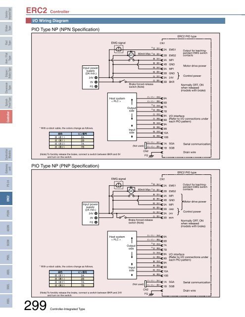
I/O Wiring Diagram<br />
Slider<br />
Type<br />
PIO Type NP (NPN Specification)<br />
ERC2 PIO type<br />
Rod<br />
Type<br />
EMG signal<br />
CN1<br />
Arm / Flat<br />
Type<br />
Gripper /<br />
Rotary Type<br />
Cleanroom<br />
Type<br />
Input power<br />
supply<br />
(2A min.)<br />
24V<br />
0V<br />
FG<br />
MC<br />
<br />
<br />
2A<br />
60mA Max <br />
<br />
2B<br />
<br />
<br />
<br />
<br />
<br />
<br />
Brake forced-release<br />
switch (Note)<br />
4A<br />
4B<br />
5A<br />
5B<br />
3A<br />
3B<br />
EMS1<br />
EMS2<br />
MPI<br />
GND<br />
MPI<br />
GND<br />
24V<br />
BKR<br />
Output for teachingpendant<br />
EMG switch<br />
contacts<br />
Motor drive power<br />
Control power<br />
Normally OFF, ON<br />
when released<br />
(models with brake)<br />
Splash<br />
Proof Type<br />
<strong>Controller</strong><br />
<strong>Controller</strong><br />
Models<br />
Gateway<br />
unit<br />
* With a robot cable, the colors change as follows.<br />
<br />
<br />
<br />
<br />
<br />
<br />
2A<br />
2B<br />
7A<br />
7B<br />
Host system<br />
< PLC ><br />
(Note) To forcibly release the brake, connect a switch between BKR and 0V<br />
and turn on the switch.<br />
PIO Type NP (PNP Specification)<br />
Output<br />
side<br />
Input<br />
side<br />
(Not used)<br />
<br />
6A<br />
<br />
6B<br />
<br />
<br />
7A<br />
CN2<br />
FG<br />
<br />
<br />
7B<br />
<br />
8A<br />
<br />
8B<br />
<br />
9A<br />
<br />
9B<br />
<br />
10A<br />
<br />
<br />
<br />
10B<br />
1A<br />
1B<br />
I/O interface<br />
(Refer to I/O connections under<br />
each PIO pattern)<br />
SGA<br />
SGB<br />
Serial communication<br />
Drain wire<br />
ERC2 PIO type<br />
PSEL SCON ACON PCON ERC2 PS-24<br />
XSEL SSEL ASEL<br />
* With a robot cable, the colors change as follows.<br />
<br />
<br />
<br />
<br />
<br />
Input power<br />
supply<br />
(2A min.)<br />
24V<br />
<br />
2A<br />
2B<br />
7A<br />
7B<br />
(Note) To forcibly release the brake, connect a switch between BKR and 24V<br />
and turn on the switch.<br />
299 <strong>Controller</strong>-Integrated Type<br />
0V<br />
FG<br />
EMG signal<br />
Host system<br />
< PLC ><br />
MC<br />
CN1<br />
<br />
2A<br />
4A<br />
4B<br />
5A<br />
5B<br />
3A<br />
3B<br />
<br />
6A<br />
<br />
6B<br />
<br />
<br />
7A<br />
<br />
7B<br />
<br />
8A<br />
<br />
8B<br />
<br />
9A<br />
<br />
9B<br />
<br />
10A<br />
10B<br />
1A<br />
1B<br />
EMS1<br />
60mA Max <br />
<br />
2B EMS2<br />
(Not used)<br />
CN2<br />
FG<br />
<br />
Brake forced-release<br />
switch (Note)<br />
Output<br />
side<br />
Input<br />
side<br />
<br />
<br />
<br />
<br />
<br />
<br />
<br />
<br />
<br />
<br />
MPI<br />
GND<br />
MPI<br />
<br />
<br />
<br />
SGA<br />
SGB<br />
Output for teachingpendant<br />
EMG switch<br />
contacts<br />
Motor drive power<br />
Control power<br />
Normally OFF, ON<br />
when released<br />
(models with brake)<br />
I/O interface<br />
(Refer to I/O connections under<br />
each PIO pattern)<br />
Serial communication<br />
Drain wire


