

Controller
Controller
Controller

Create successful ePaper yourself
Turn your PDF publications into a flip-book with our unique Google optimized e-Paper software.
<strong>Controller</strong> -<br />
Integrated Type<br />
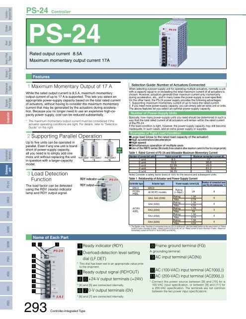
PS-24 <strong>Controller</strong><br />
Slider<br />
Type<br />
Rod<br />
Type<br />
PS-24<br />
Arm / Flat<br />
Type<br />
Rated output current 8.5A<br />
Maximum momentary output current 17A<br />
Gripper /<br />
Rotary Type<br />
Features<br />
Cleanroom<br />
Type<br />
Splash<br />
Proof Type<br />
<strong>Controller</strong><br />
<strong>Controller</strong><br />
Models<br />
Gateway<br />
unit<br />
PSEL SCON ACON PCON ERC2 PS-24<br />
XSEL SSEL ASEL<br />
1 Maximum Momentary Output of 17 A<br />
While the rated output current is 8.5 A, maximum momentary<br />
output current of up to 17 A is supported. This lets you select an<br />
appropriate power-supply capacity based on the total rated current<br />
of actuators, without having to consider the maximum momentary<br />
current that may be generated by the actuators during acceleration.<br />
Because you no longer need to use an expensive high-capacity<br />
power supply, cost can be reduced substantially.<br />
* The maximum momentary output current must be considered if the<br />
actuator operating conditions are tight. For details, refer to “Selection<br />
Guide” on the right.<br />
2 Supporting Parallel Operation<br />
Up to five units can be operated in<br />
parallel. Even if any one unit is found<br />
short of power-supply capacity,<br />
all you need is to simply add one<br />
more unit without replacing the unit<br />
in question with a larger-capacity<br />
model.<br />
3 Load Detection<br />
Function<br />
The load factor can be detected<br />
using the RDY (ready) indicator<br />
lamp and RDY output signal.<br />
Name of Each Part<br />
3<br />
4<br />
5<br />
6<br />
7<br />
8<br />
9<br />
10<br />
11<br />
293 <strong>Controller</strong>-Integrated<br />
2 1<br />
Type<br />
+<br />
+<br />
Power supply 1 Power supply 2<br />
– –<br />
RDY indicator<br />
RDY output<br />
+<br />
Power supply 3<br />
–<br />
Load<br />
1 Ready indicator (RDY)<br />
Selection Guide: Number of Actuators Connected<br />
When selecting a power-supply unit for operating multiple actuators, normally a unit<br />
with a capacity equal to or exceeding the total maximum current of all actuators is<br />
chosen. However, actuators generate their maximum current only momentarily<br />
during acceleration, etc., and in many cases the power-supply is over-specified.<br />
On the other hand, the PS-24 power supply provides the following advantages:<br />
1. Supporting maximum momentary current of up to twice the rated current.<br />
2. If you need more power-supply capacity, you can simply add an extra unit or units.<br />
The above features let you select an optimal power-supply capacity.<br />
Number of Power-Supply Units<br />
Basically, how many power-supply units you need should be determined in such a<br />
way that the total rated current of all actuators will remain within the rated current<br />
of the PS-24.<br />
If the load condition is tight, however, the power-supply capacity may still become<br />
inadequate. In such cases, add an extra power supply or supplies.<br />
Examples of Tight Load Condition<br />
Large load (close to the rated load capacity of the actuator)<br />
High acceleration/deceleration<br />
High speed<br />
Simultaneous operation of multiple axes<br />
Use of the RB75 series (Structurally these actuators allow maximum current to flow for a longer period.)<br />
Table 1. Rated Current of PS-24 and Allowable Maximum Momentary Current<br />
Number of connected units<br />
1 unit<br />
2 unit<br />
3 unit<br />
4 unit<br />
5 unit<br />
Rated current [A]<br />
8.5<br />
15.3<br />
22.95<br />
30.6<br />
38.25<br />
Maximum momentary current [A]<br />
17<br />
30.6<br />
45.9<br />
61.2<br />
76.5<br />
Note) Consider a safety factor (loss) of 10% for the second and subsequent units.<br />
Table 1. Relationship of Actuator and Power-Supply Current<br />
<strong>Controller</strong> type Actuator type Power-supply current [A]<br />
Number of connected axes<br />
per PS-24 (reference) *1<br />
ERC2<br />
PCON<br />
PSEL<br />
ACON<br />
ASEL<br />
2 Overload-detection level setting<br />
dial (LF.DET)<br />
* This dial has been set to an appropriate value prior<br />
to the shipment.<br />
3 Ready output signal (RDYOUT)<br />
4 5 +24-V output terminals (+24V)<br />
* [4] and [5] are connected internally.<br />
6 7 0-V output terminals (0V)<br />
* [6] and [7] are connected internally.<br />
ERC2<br />
All RCP2 models<br />
SA4, SA5 (20W)<br />
SA6 (30W)<br />
RA3 (20W)<br />
RA4 (20W)<br />
RA4 (30W)<br />
Rating<br />
(= Max.) 2A<br />
Rating<br />
Max.<br />
Rating<br />
Max.<br />
Rating<br />
Max.<br />
Rating<br />
Max.<br />
Rating<br />
1.3A<br />
3.7A<br />
1.3A<br />
4.2A<br />
1.7A<br />
5A<br />
1.3A<br />
3.7A<br />
1.3A<br />
Max. 4.2A<br />
*1 The figures under “Number of connected axes per PS-24 (reference)” are calculated based on the assumption of “Rated<br />
current of axis x Number of axes < Rated current of PS-24 (8.5 A)” [or “Rated current of axis x Number of axes < Maximum<br />
momentary current of PS-24 (17 A) for ERC2 and RCP2].<br />
8 Frame ground terminal (FG)<br />
A grounding terminal.<br />
9 AC input terminal (AC(N))<br />
10AC (100-VAC) input terminal (AC100(L))<br />
11AC (200-VAC) input terminal (AC200(L))<br />
* Connect the power source between [9] and [10] for a<br />
100-VAC input specification, or between [9] and [11] for<br />
a 200-VAC specification. The terminals are not common<br />
between the two power input specifications.<br />
8<br />
6<br />
6<br />
5<br />
6<br />
6


