

Controller
Controller
Controller

Create successful ePaper yourself
Turn your PDF publications into a flip-book with our unique Google optimized e-Paper software.
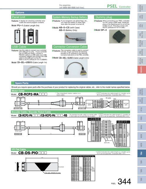
Options<br />
For enquiries,<br />
call 0800-888-0088 (toll-free).<br />
PSEL <strong>Controller</strong><br />
<strong>Controller</strong> -<br />
Integrated Type<br />
Panel Unit<br />
Features A display for checking controller error<br />
codes and active program numbers.<br />
Model PU—1 (Cable Length 3m)<br />
ø3.2 17<br />
43<br />
System-Memory Backup Battery<br />
Features<br />
Model<br />
If your programs use global flags, etc.,<br />
you need this battery to retain data<br />
even after the power is turned off.<br />
AB—5—CS (with Case)<br />
AB—5 (Battery Only)<br />
Dummy plug<br />
Features<br />
Model DP—3<br />
When connecting your PSEL controller<br />
to a PC using a USB cable, install this<br />
plug on the teaching port to cut off the<br />
enable circuit. (This plug comes with<br />
the PC software IA-101-X-USB.)<br />
Slider<br />
Type<br />
Rod<br />
Type<br />
114<br />
Arm / Flat<br />
Type<br />
USB Cable<br />
Features Use this cable to connect your controller<br />
with USB port to a PC. If your controller<br />
has no USB port (XSEL), connect a<br />
RS232C cable to a USB cable via a USB<br />
conversion adapter and connect the USB<br />
cable to the USB port on the PC.<br />
(Refer to the PC software IA-101-X-USBMW.)<br />
Model CB—SEL—USB010 (Cable Length 1m)<br />
Connector Conversion Cable<br />
This conversion cable is used to connect<br />
Features<br />
a D-sub, 25-pin connector for teaching<br />
pendant or PC software to the teaching<br />
connector (half-pitch) on the PSEL controller.<br />
Model CB—SEL—SJ002 (Cable Length 0.2m)<br />
Gripper /<br />
Rotary Type<br />
Cleanroom<br />
Type<br />
Splash<br />
Proof Type<br />
<strong>Controller</strong><br />
(15)<br />
Spare Parts<br />
Should you require spare parts after the purchase of your product for replacing the original cables, etc., refer to the model names specified below.<br />
Motor Cable<br />
Model CB-RCP2-MA c c c<br />
(8)<br />
(Front view)<br />
<strong>Controller</strong> end<br />
(18)<br />
(20)<br />
CN3<br />
CN4<br />
(ø8)<br />
Encoder Cable / Encoder Robot Cable<br />
Model CB-RCP2-PA c c c /CB-RCP2-PA c c c -RB<br />
L<br />
L<br />
* The standard motor cable is a<br />
robot cable.<br />
(28)<br />
C<br />
N<br />
1<br />
(20)<br />
(14)<br />
(14)<br />
(Front view)<br />
Actuator end<br />
(5) (8) (13) (15)<br />
(Front view)<br />
<strong>Controller</strong> end<br />
I/O Flat Cable<br />
Model CB-DS-PIO c c c<br />
1B<br />
17B<br />
1A<br />
17A<br />
(ø9)<br />
2m<br />
Flat cable, AWG28 (34 cores)<br />
(35)<br />
No connector<br />
C<br />
N<br />
2<br />
(Front view)<br />
(25)<br />
Actuator end<br />
I-1318119-3<br />
(AMP)<br />
CN4<br />
PHDR-16VS<br />
(JST)<br />
No. Color Wire No. Color<br />
1A<br />
1B<br />
2A<br />
2B<br />
3A<br />
3B<br />
4A<br />
<br />
<br />
<br />
<br />
<br />
<br />
<br />
9B<br />
10A<br />
10B<br />
11A<br />
11B<br />
12A<br />
12B<br />
<br />
<br />
<br />
<br />
<br />
<br />
<br />
4B Flat 13A <br />
5A <br />
cable 13B <br />
5B<br />
(pressure-<br />
14A <br />
welded)<br />
6A 14B <br />
6B<br />
7A<br />
7B<br />
8A<br />
8B<br />
9A<br />
<br />
<br />
<br />
<br />
<br />
<br />
15A<br />
15B<br />
16A<br />
16B<br />
17A<br />
17B<br />
<br />
<br />
<br />
<br />
<br />
<br />
<br />
<br />
<br />
<br />
<br />
<br />
* The standard encoder cable is a normal cable.<br />
A robot cable can be specified as an option.<br />
Cable<br />
color<br />
–<br />
–<br />
1<br />
<br />
<br />
<br />
<br />
<br />
<br />
<br />
<br />
<br />
–<br />
–<br />
–<br />
Drain<br />
Wire<br />
Flat<br />
cable<br />
(pressurewelded)<br />
* c c c indicates the cable length (L). Lengths up to<br />
20 m can be specified. Example) 080 = 8 m<br />
CN3<br />
A A1<br />
VMM A2<br />
B A3<br />
A B1<br />
VMM B2<br />
B B3<br />
Signal<br />
name number<br />
Pin<br />
(BAT2) 16<br />
(BAT1) 15<br />
BK+ 14<br />
BK– 13<br />
ENA 12<br />
ENA 11<br />
ENB 10<br />
ENB 9<br />
– 8<br />
VPS 7<br />
VBB 6<br />
GND 5<br />
(N.C) 4<br />
(N.C) 3<br />
(N.C) 2<br />
F.G 1<br />
M cable<br />
Shield wire<br />
Drain wire<br />
CN1<br />
1<br />
2<br />
3<br />
4<br />
5<br />
6<br />
A<br />
VMM<br />
A<br />
B<br />
VMM<br />
B<br />
number<br />
1<br />
2<br />
3<br />
4<br />
5<br />
6<br />
7<br />
8<br />
9<br />
10<br />
11<br />
12<br />
13<br />
14<br />
15<br />
16<br />
17<br />
18<br />
<br />
<br />
<br />
<br />
<br />
<br />
name<br />
ENA<br />
ENA<br />
ENB<br />
ENB<br />
–<br />
–<br />
–<br />
–<br />
GND<br />
VBB<br />
VPS<br />
–<br />
–<br />
–<br />
–<br />
BK+<br />
BK–<br />
F.G<br />
SLP-06V<br />
(JST)<br />
* c c c indicates the cable length (L). Lengths up<br />
to 20 m can be specified. Example) 080 = 8 m<br />
Pin Signal Cable<br />
color<br />
<br />
<br />
<br />
<br />
–<br />
–<br />
–<br />
–<br />
<br />
<br />
<br />
–<br />
–<br />
–<br />
–<br />
<br />
<br />
Drain<br />
CN2<br />
XMP-18V<br />
(JST)<br />
* c c c indicates the cable length (L). Lengths up to<br />
10 m can be specified. Example) 080 = 8 m<br />
PSEL 344<br />
<strong>Controller</strong><br />
Models<br />
Gateway<br />
unit<br />
PS-24<br />
ERC2<br />
PCON<br />
ACON<br />
SCON<br />
PSEL<br />
ASEL<br />
SSEL<br />
XSEL


