

Controller
Controller
Controller

You also want an ePaper? Increase the reach of your titles
YUMPU automatically turns print PDFs into web optimized ePapers that Google loves.
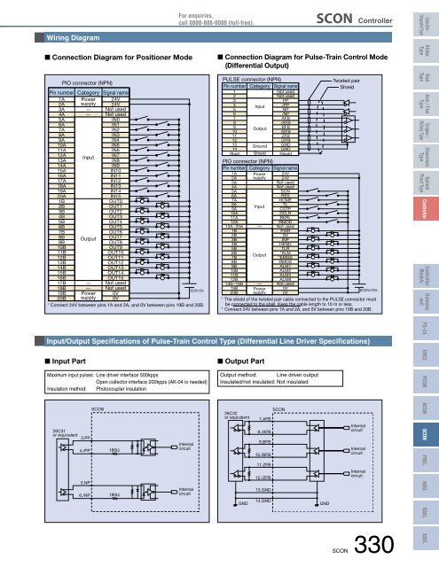
Wiring Diagram<br />
For enquiries,<br />
call 0800-888-0088 (toll-free).<br />
SCON <strong>Controller</strong><br />
<strong>Controller</strong> -<br />
Integrated Type<br />
n Connection Diagram for Positioner Mode<br />
PIO connector (NPN)<br />
Pin number Category Signal name<br />
1A Power 24V<br />
2A supply 24V<br />
3A<br />
4A<br />
5A<br />
6A<br />
7A<br />
8A<br />
9A<br />
10A<br />
11A<br />
—<br />
—<br />
Not used<br />
Not used<br />
IN0<br />
IN1<br />
IN2<br />
IN3<br />
IN4<br />
IN5<br />
IN6<br />
12A<br />
Input<br />
IN7<br />
13A<br />
IN8<br />
14A<br />
15A<br />
16A<br />
17A<br />
18A<br />
19A<br />
20A<br />
1B<br />
2B<br />
3B<br />
4B<br />
5B<br />
6B<br />
7B<br />
IN9<br />
IN10<br />
IN11<br />
IN12<br />
IN13<br />
IN14<br />
IN15<br />
OUT0<br />
OUT1<br />
OUT2<br />
OUT3<br />
OUT4<br />
OUT5<br />
OUT6<br />
8B Output OUT7<br />
9B<br />
OUT8<br />
10B<br />
11B<br />
12B<br />
13B<br />
14B<br />
15B<br />
16B<br />
17B —<br />
OUT9<br />
OUT10<br />
OUT11<br />
OUT12<br />
OUT13<br />
OUT14<br />
OUT15<br />
Not used<br />
18B — Not used<br />
DC24V±10%<br />
19B Power 0V<br />
20B supply 0V<br />
* Connect 24V between pins 1A and 2A, and 0V between pins 19B and 20B.<br />
n Connection Diagram for Pulse-Train Control Mode<br />
(Differential Output)<br />
PULSE connector (NPN)<br />
Pin number Category Signal name<br />
1<br />
2<br />
3<br />
4<br />
5<br />
6<br />
7<br />
8<br />
9<br />
10<br />
11<br />
12<br />
13<br />
14<br />
Shell<br />
Input<br />
Output<br />
Ground<br />
Shield<br />
Not used<br />
Not used<br />
PP<br />
/PP<br />
NP<br />
/NP<br />
AFB<br />
/AFB<br />
BFB<br />
/BFB<br />
ZFB<br />
/ZFB<br />
GND<br />
GND<br />
Shield<br />
PIO connector (NPN)<br />
Pin number Category Signal name<br />
1A Power 24V<br />
2A supply 24V<br />
3A<br />
Not used<br />
4A<br />
Not used<br />
5A<br />
SON<br />
6A<br />
RES<br />
7A<br />
HOME<br />
8A<br />
TL<br />
Input<br />
9A<br />
CSTP<br />
10A<br />
DCLR<br />
11A<br />
BKRL<br />
12A<br />
RMOD<br />
13A~20A — Not used<br />
1B<br />
PWR<br />
2B<br />
SV<br />
3B<br />
INP<br />
4B<br />
HEND<br />
5B<br />
TLR<br />
6B<br />
*ALM<br />
Output<br />
7B<br />
*EMGS<br />
8B<br />
RMDS<br />
9B<br />
ALM1<br />
10B<br />
ALM2<br />
11B<br />
ALM4<br />
12B<br />
ALM8<br />
13B~18B — Not used<br />
19B Power 0V<br />
20B supply 0V<br />
Twisted pair<br />
Shield<br />
DC24V±10%<br />
* The shield of the twisted pair cable connected to the PULSE connector must<br />
be connected to the shell. Keep the cable length to 10 m or less.<br />
* Connect 24V between pins 1A and 2A, and 0V between pins 19B and 20B.<br />
Slider<br />
Type<br />
Rod<br />
Type<br />
Arm / Flat<br />
Type<br />
Gripper /<br />
Rotary Type<br />
Cleanroom<br />
Type<br />
Splash<br />
Proof Type<br />
<strong>Controller</strong><br />
<strong>Controller</strong><br />
Models<br />
Gateway<br />
unit<br />
Input/Output Specifications of Pulse-Train Control Type (Differential Line Driver Specifications)<br />
PS-24<br />
n Input Part<br />
Maximum input pulses: Line driver interface 500kpps<br />
Open collector interface 200kpps (AK-04 is needed)<br />
Insulation method: Photocoupler insulation<br />
n Output Part<br />
Output method: Line driver output<br />
Insulated/not insulated: Not insulated<br />
ERC2<br />
PCON<br />
26C31<br />
or equivalent<br />
3.PP<br />
4./PP<br />
5.NP<br />
6./NP<br />
SCON<br />
180Ω<br />
180Ω<br />
Internal<br />
circuit<br />
Internal<br />
circuit<br />
26C32<br />
or equivalent<br />
GND<br />
SCON<br />
7.AFB<br />
8./AFB<br />
9.BFB<br />
10./BFB<br />
11.ZFB<br />
12./ZFB<br />
13.GND<br />
14.GND<br />
GND<br />
Internal<br />
circuit<br />
Internal<br />
circuit<br />
Internal<br />
circuit<br />
ACON SCON PSEL ASEL<br />
SSEL<br />
SCON 330<br />
XSEL


