

Controller
Controller
Controller

Create successful ePaper yourself
Turn your PDF publications into a flip-book with our unique Google optimized e-Paper software.
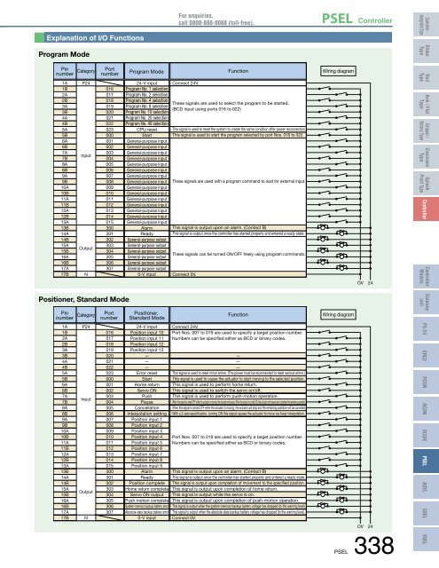
Explanation of I/O Functions<br />
For enquiries,<br />
call 0800-888-0088 (toll-free).<br />
PSEL <strong>Controller</strong><br />
<strong>Controller</strong> -<br />
Integrated Type<br />
Program Mode<br />
Slider<br />
Type<br />
Pin<br />
number<br />
1A<br />
1B<br />
2A<br />
2B<br />
3A<br />
3B<br />
4A<br />
4B<br />
5A<br />
5B<br />
6A<br />
6B<br />
7A<br />
7B<br />
8A<br />
8B<br />
9A<br />
9B<br />
10A<br />
10B<br />
11A<br />
11B<br />
12A<br />
12B<br />
13A<br />
13B<br />
14A<br />
14B<br />
15A<br />
15B<br />
16A<br />
16B<br />
17A<br />
17B<br />
Category<br />
P24<br />
Input<br />
Output<br />
N<br />
Port<br />
number<br />
016<br />
017<br />
018<br />
019<br />
020<br />
021<br />
022<br />
023<br />
000<br />
001<br />
002<br />
003<br />
004<br />
005<br />
006<br />
007<br />
008<br />
009<br />
010<br />
011<br />
012<br />
013<br />
014<br />
015<br />
300<br />
301<br />
302<br />
303<br />
304<br />
305<br />
306<br />
307<br />
Program Mode<br />
24-V input<br />
Program No. 1 selection<br />
Program No. 2 selection<br />
Program No. 4 selection<br />
Program No. 8 selection<br />
Program No. 10 selection<br />
Program No. 20 selection<br />
Program No. 40 selection<br />
CPU reset<br />
Start<br />
General-purpose input<br />
General-purpose input<br />
General-purpose input<br />
General-purpose input<br />
General-purpose input<br />
General-purpose input<br />
General-purpose input<br />
General-purpose input<br />
General-purpose input<br />
General-purpose input<br />
General-purpose input<br />
General-purpose input<br />
General-purpose input<br />
General-purpose input<br />
General-purpose input<br />
Alarm<br />
Ready<br />
General-purpose output<br />
General-purpose output<br />
General-purpose output<br />
General-purpose output<br />
General-purpose output<br />
General-purpose output<br />
0-V input<br />
Connect 24V.<br />
Function<br />
These signals are used to select the program to be started.<br />
(BCD input using ports 016 to 022)<br />
This signal is used to reset the system to create the same condition after power reconnection.<br />
This signal is used to start the program selected by port Nos. 016 to 022.<br />
These signals are used with a program command to wait for external input.<br />
This signal is output upon an alarm. (Contact B)<br />
This signal is output once the controller has started properly and entered a ready state.<br />
These signals can be turned ON/OFF freely using program commands.<br />
Connect 0V.<br />
Wiring diagram<br />
OV 24<br />
Rod<br />
Type<br />
Arm / Flat<br />
Type<br />
Gripper /<br />
Rotary Type<br />
Cleanroom<br />
Type<br />
Splash<br />
Proof Type<br />
<strong>Controller</strong><br />
<strong>Controller</strong><br />
Models<br />
Positioner, Standard Mode<br />
Pin<br />
number<br />
1A<br />
1B<br />
2A<br />
2B<br />
3A<br />
3B<br />
4A<br />
4B<br />
5A<br />
5B<br />
6A<br />
6B<br />
7A<br />
7B<br />
8A<br />
8B<br />
9A<br />
9B<br />
10A<br />
10B<br />
11A<br />
11B<br />
12A<br />
12B<br />
13A<br />
13B<br />
14A<br />
14B<br />
15A<br />
15B<br />
16A<br />
16B<br />
17A<br />
17B<br />
Category<br />
P24<br />
Input<br />
Output<br />
N<br />
Port<br />
number<br />
016<br />
017<br />
018<br />
019<br />
020<br />
021<br />
022<br />
023<br />
000<br />
001<br />
002<br />
003<br />
004<br />
005<br />
006<br />
007<br />
008<br />
009<br />
010<br />
011<br />
012<br />
013<br />
014<br />
015<br />
300<br />
301<br />
302<br />
303<br />
304<br />
305<br />
306<br />
307<br />
Positioner,<br />
Standard Mode<br />
24-V input<br />
Position input 10<br />
Position input 11<br />
Position input 12<br />
Position input 13<br />
—<br />
—<br />
—<br />
Error reset<br />
Start<br />
Home return<br />
Servo ON<br />
Push<br />
Pause<br />
Cancellation<br />
Interpolation setting<br />
Position input 1<br />
Position input 2<br />
Position input 3<br />
Position input 4<br />
Position input 5<br />
Position input 6<br />
Position input 7<br />
Position input 8<br />
Position input 9<br />
Alarm<br />
Ready<br />
Position complete<br />
Home return complete<br />
Servo ON output<br />
Push motion complete<br />
System-memory backup battery error<br />
Absolute-data backup battery error<br />
0-V input<br />
Function<br />
Connect 24V.<br />
Port Nos. 007 to 019 are used to specify a target position number.<br />
Numbers can be specified either as BCD or binary codes.<br />
—<br />
—<br />
—<br />
This signal is used to reset minor errors. (The power must be reconnected to reset serious errors.)<br />
This signal is used to cause the actuator to start moving to the selected position.<br />
This signal is used to perform home return.<br />
This signal is used to switch the servo on/off.<br />
This signal is used to perform push-motion operation.<br />
When this signal is turned OFF while the actuator is moving, the actuator will pause. When the signal is turned ON, the actuator will resume and complete the remaining operation.<br />
When this signal is turned OFF while the actuator is moving, the actuator will stop and the remaining operation will be cancelled.<br />
With a 2-axis specification, turning ON this signal causes the actuator to move via linear interpolation.<br />
Port Nos. 007 to 019 are used to specify a target position number.<br />
Numbers can be specified either as BCD or binary codes.<br />
This signal is output upon an alarm. (Contact B)<br />
This signal is output once the controller has started properly and entered a ready state.<br />
This signal is output upon completion of movement to the specified position.<br />
This signal is output upon completion of home return.<br />
This signal is output while the servo is on.<br />
This signal is output upon completion of push-motion operation.<br />
This signal is output when the system-memory backup battery voltage has dropped (to the warning level).<br />
This signal is output when the absolute-data backup battery voltage has dropped (to the warning level).<br />
Connect 0V.<br />
Wiring diagram<br />
OV 24<br />
PSEL 338<br />
Gateway<br />
unit<br />
PS-24<br />
ERC2<br />
PCON<br />
ACON<br />
SCON<br />
PSEL<br />
ASEL<br />
SSEL<br />
XSEL


