Kent Design - Technical Appendix - Kent County Council
Kent Design - Technical Appendix - Kent County Council
Kent Design - Technical Appendix - Kent County Council

Create successful ePaper yourself
Turn your PDF publications into a flip-book with our unique Google optimized e-Paper software.
2.2 GEOMETRIC REQUIREMENTS FOR RESIDENTIAL<br />
ROADS<br />
2.2.1 TURNING FACILITIES<br />
2.2.1.1 GENERAL<br />
Turning facilities shall be provided wherever vehicles would otherwise<br />
have to reverse over long distances or whenever they might turn in<br />
locations which could cause damage to adjacent verges or footways.<br />
Depending upon the degree of inconvenience which could be<br />
caused, turning areas may be provided as parts of junctions.<br />
The spacing, layout and dimensions of turning areas should be<br />
designed to cater for the category and size of vehicle normally<br />
expected to use them. The following criteria however, needs to be<br />
taken into account when designing turning areas:<br />
• Refuse and large service vehicles should not be expected<br />
to reverse more than 40m.<br />
• Pantechnicons should not be expected to reverse more<br />
than 60m<br />
• Cars and smaller service vehicles should not be expected<br />
to reverse more than 25m<br />
The siting of turning areas should aim to minimise the likelihood of<br />
vehicles using them for parking. Indiscriminate parking can be<br />
discouraged if the turning area provides direct access into the<br />
curtilage or parking areas of adjacent dwellings. However where<br />
casual parking is permitted outside the area required for turning,<br />
spaces shall be located carefully between driveways as shown in fig 6.<br />
2.2.2 GRADIENTS<br />
2.2.2.1 GENERAL<br />
When designing roads there is a tendency to use steep gradients to<br />
avoid excessive cut and fill of the natural landscape. However, in<br />
order to minimise the dangers of icy conditions and improve road<br />
safety on bends and at junctions, there is a need to restrict the<br />
maximum acceptable gradients. Similarly to assist in draining the road<br />
and preventing ponding areas, there is a need to restrict the<br />
minimum acceptable gradients.<br />
Where changes in gradient occur, vertical curves are required at<br />
summits and sags both for ease and comfort of driving, and at summits<br />
in particular to ensure adequate forward visibility along the carriageway.<br />
2.2.2.2 LONGITUDINAL GRADIENTS<br />
The maximum and minimum longitudinal gradients for residential<br />
roads should be restricted in line with the following recommendations.<br />
MAXIMUM LONGITUDINAL GRADIENTS<br />
• All vehicle, pedestrian and cycle dominated<br />
environments, except shared surface environments<br />
6% (1 in 16.7)<br />
• Shared surface environments 7% (1 in 14.3)<br />
MINIMUM LONGITUDINAL GRADIENTS<br />
• All environments (flexible surfacing) 0.8% (1 in 125)<br />
• All environments (block paving surfacing) 1.25% (1 in 80)<br />
Industrial and Commercial Road gradients shall be in accordance with<br />
section 2.3.<br />
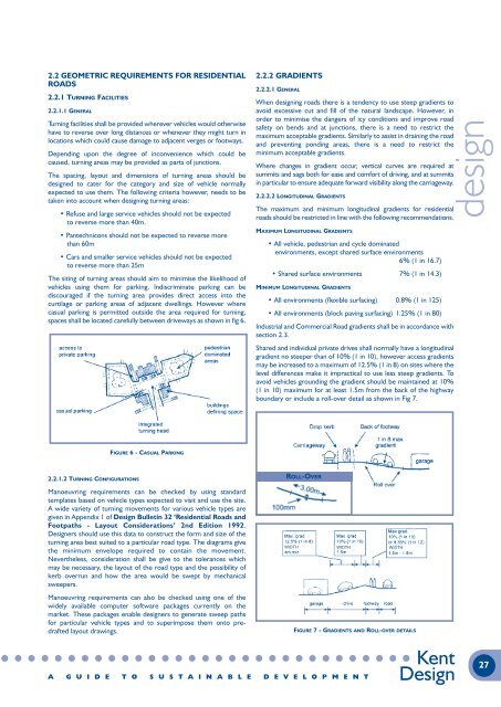
Shared and individual private drives shall normally have a longitudinal<br />
gradient no steeper than of 10% (1 in 10), however access gradients<br />
may be increased to a maximum of 12.5% (1 in 8) on sites where the<br />
level differences make it impractical to use less steep gradients. To<br />
avoid vehicles grounding the gradient should be maintained at 10%<br />
(1 in 10) maximum for at least 1.5m from the back of the highway<br />
boundary or include a roll-over detail as shown in Fig 7.<br />
design<br />
FIGURE 6 - CASUAL PARKING<br />
2.2.1.2 TURNING CONFIGURATIONS<br />
ROLL-OVER<br />
Manoeuvring requirements can be checked by using standard<br />
templates based on vehicle types expected to visit and use the site.<br />
A wide variety of turning movements for various vehicle types are<br />
given in <strong>Appendix</strong> 1 of <strong>Design</strong> Bulletin 32 ‘Residential Roads and<br />
Footpaths - Layout Considerations’ 2nd Edition 1992.<br />
<strong>Design</strong>ers should use this data to construct the form and size of the<br />
turning area best suited to a particular road type. The diagrams give<br />
the minimum envelope required to contain the movement.<br />
Nevertheless, consideration shall be give to the tolerances which<br />
may be necessary, the layout of the road type and the possibility of<br />
kerb overrun and how the area would be swept by mechanical<br />
sweepers.<br />
Manoeuvring requirements can also be checked using one of the<br />
widely available computer software packages currently on the<br />
market. These packages enable designers to generate sweep paths<br />
for particular vehicle types and to superimpose them onto predrafted<br />
layout drawings.<br />
WIDTH WIDTH WIDTH<br />
FIGURE 7 - GRADIENTS AND ROLL-OVER DETAILS<br />
A G U I D E T O S U S T A I N A B L E D E V E L O P M E N T<br />
<strong>Kent</strong><br />
<strong>Design</strong><br />
27