Kent Design - Technical Appendix - Kent County Council
Kent Design - Technical Appendix - Kent County Council
Kent Design - Technical Appendix - Kent County Council

You also want an ePaper? Increase the reach of your titles
YUMPU automatically turns print PDFs into web optimized ePapers that Google loves.
A separate chemical contamination risk assessment should also be<br />
undertaken for the whole development.<br />
3.2.1.3 SUB-SOIL DRAINAGE<br />
Every endeavour should be made to prevent the water table from<br />
rising to within 600mm of formation level. Methods of preventing this<br />
should be discussed with the Engineer at time of designing the works<br />
3.2.1.4 EARTHWORKS<br />
All turf and topsoil shall be removed from the formation of the new road.<br />
It shall be stored carefully on site up to a maximum of 2m in height to<br />
prevent deterioration and contamination with sub-soil etc and shall<br />
wherever possible be reused within the site. Only with the agreement of<br />
the Engineer may surplus material be removed from the site.<br />
If in-situ stabilisation of the existing soil is to be used instead of<br />
imported granular capping layer there will be considerably less<br />
material to be removed<br />
Other organic materials within the site of the new road shall be<br />
identified, removed and their disposal agreed with the Engineer.<br />
Wherever possible they shall be reused within the site by the<br />
construction of appropriate mounds/landscaping features.<br />
The area of the carriageway shall be excavated or filled to produce<br />
the formation level.<br />
Where local areas are uncovered which are softer than the general<br />
sub-grade they shall be excavated out to a depth appropriate for the<br />
soft area and backfilled with material similar to the surrounding<br />
formation. Where soft areas exceed 25% of the total area of<br />
carriageway in which they occur, the whole area shall be reduced in<br />
level and suitable material substituted. All other unsuitable material,<br />
other than organic material, shall be considered for treatment to<br />
make it suitable for use in the carriageway works, footways, verges<br />
or other parts of the site. Only with the agreement of the Engineer<br />
may surplus material be removed from the site.<br />
Fill material shall comply with ‘suitable material’ as defined in the<br />
Specification.<br />
3.2.1.5 SERVICE DUCTS AND PIPEWORK<br />
Ducts and pipework shall wherever possible not be located in the<br />
carriageway. Where service crossings make this unavoidable, they<br />
shall be installed prior to carriageway construction and protected<br />
from damage by subsequent construction.<br />
3.3 CARRIAGEWAY- SUB-BASE AND CAPPING LAYER<br />
3.3.1.1 SUB -BASE AND CAPPING LAYER DESIGN THICKNESS<br />
For District Distributor roads and Industrial Access Roads the thickness<br />
of sub-base shall be determined in accordance with the <strong>Design</strong><br />
Manual for Road and Bridge Works Volume 7 Section 2 Chapter<br />
3 HD25 for the estimated volume of traffic as agreed with the Engineer.<br />
Only ‘Flexible pavements’ are permitted. Where the capping layer<br />
option is preferred, the reasons for not improving the CBR of the subgrade<br />
by stabilisation shall be discussed with the Engineer<br />
For Local Distributor, Major Access Roads, Minor Access Roads, Minor<br />
Access Ways and Homezones the design process shall be as follows:<br />
Carry out four thickness designs using the equilibrium CBR of the<br />
formation for the long term condition and the anticipated CBR at the<br />
time of construction for the short term condition. The latter will<br />
need to be rechecked at time of construction.<br />
Select the thickness for sub-base alone and for Capping layer options<br />
which are the more conservative.<br />
Determine on economic practicality or sustainability grounds<br />
whether to use the sub-base option or capping layer option.<br />
It is not intended that the sub-base be used as a access for the construction<br />
of buildings. Access should be provided separately or by using the surface<br />
of the basecourse prior to laying the blacktop or block surfacing.<br />
The thickness design below is based on the works being carried out by a<br />
company quality assured for this activity. Records of the CBR at the time<br />
of construction, the thickness of the laid materials and the compaction<br />
plant used shall be made available to the Engineer. Where the works are<br />
not carried out by a company quality assured for this activity, the thickness<br />
of sub-base and capping shall each be increased by 20%.<br />
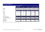
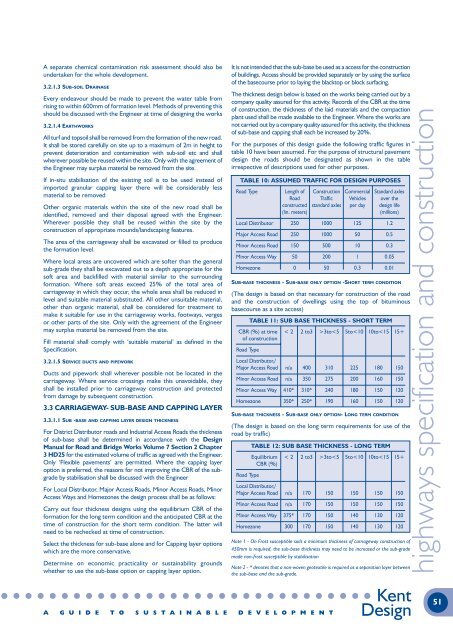
For the purposes of this design guide the following traffic figures in<br />
table 10 have been assumed. For the purpose of structural pavement<br />
design the roads should be designated as shown in the table<br />
irrespective of descriptions used for other purposes.<br />
TABLE 10: ASSUMED TRAFFIC FOR DESIGN PURPOSES<br />
Road Type Length of Construction Commercial Standard axles<br />
Road Traffic Vehicles over the<br />
constructed standard axles per day design life<br />
(lin. meters)<br />
(millions)<br />
Local Distributor 250 1000 125 1.2<br />
Major Access Road 250 1000 50 0.5<br />
Minor Access Road 150 500 10 0.3<br />
Minor Access Way 50 200 1 0.05<br />
Homezone 0 50 0.3 0.01<br />
SUB-BASE THICKNESS - SUB-BASE ONLY OPTION -SHORT TERM CONDITION<br />
(The design is based on that necessary for construction of the road<br />
and the construction of dwellings using the top of bituminous<br />
basecourse as a site access)<br />
TABLE 11: SUB BASE THICKNESS - SHORT TERM<br />
CBR (%) at time < 2 2 to3 >3to