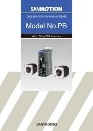
SANMOTION F2 2-phase stepper motor and driver
SANMOTION F2 2-phase stepper motor and driver
SANMOTION F2 2-phase stepper motor and driver
Create successful ePaper yourself
Turn your PDF publications into a flip-book with our unique Google optimized e-Paper software.
Input circuit configuration (CW, CCW)<br />
<br />
220<br />
Input signal<br />
DC input set model<br />
<br />
Input signal specifications<br />
Negative logic<br />
Positive logic<br />
2s MIN.<br />
1s MAX. 1s MAX.<br />
4.0 to 5.5V<br />
90<br />
4.0 to 5.5V<br />
5V <br />
90<br />
Approx. 15 mA<br />
50<br />
<br />
Rotation<br />
Approx. 15mA<br />
<br />
Rotation<br />
50<br />
<br />
0 to 0.5V<br />
10<br />
*Pulse duty 50 % MAX.<br />
10 *Pulse duty 50% MAX.<br />
0 to 0.5V<br />
1s MAX. 1s MAX.<br />
2s MIN.<br />
Timing of the comm<strong>and</strong> pulse<br />
2-input mode (CW, CCW)<br />
• The internal photo coupler turns ON within the <strong>and</strong>, at its falling edge to<br />
CW<br />
OFF, the internal circuit<strong>motor</strong>is activated.<br />
• When applying the pulse to CW, turn OFF the CCW side internal photo coupler.<br />
CCW<br />
• When applying the pulse to CCW, turn OFF the CW side internal photo coupler.<br />
50s MIN.<br />
Stepping Motor<br />
Stepping <strong>motor</strong>s with<br />
integrated <strong>driver</strong>s<br />
Stepping <strong>motor</strong> for<br />
vacuum environment<br />
Pulse <strong>and</strong> direction mode (CK, U/D)<br />
CK<br />
50s MIN.<br />
100s MIN.<br />
• TheHlevel is input for <strong>and</strong>, at its rising edge toHlevel, the internal circuit<br />
stepping <strong>motor</strong>is activated.<br />
• Switching the input signal U/D should be performed while the input level on<br />
the CK side isL.<br />
Dimensions<br />
U/D<br />
Input circuit configuration (PD, EXT, F/H, EMG)<br />
<br />
Input signal<br />
470<br />
Approx. 10mA<br />
<br />
Timing of comm<strong>and</strong> pulse, step angle selection, <strong>and</strong><br />
FULL/HALF selection input signal<br />
Comm<strong>and</strong> pulse<br />
100s MIN.<br />
EXT, F/H<br />
10s MIN.<br />
• Shaded area indicates internal photo coupler ON.<br />
• EXT input signal<br />
EXT photo coupler ONenables a function by external F/H input signal.<br />
EXT photo coupler OFFenables the setting of a number of micro steps by<br />
main unit's rotary switch S.S.<br />
• F/H input signal<br />
F/H photo coupler ONsets HALF step (2-division) operation.<br />
F/H photo coupler OFFsets FULL step (1-division) operation.<br />
• Refer to switching EXT <strong>and</strong> F/H input signal in the [FULL/HALF input signal,<br />
comm<strong>and</strong> pulse, <strong>and</strong> step angle select].<br />
• When switching the step angle by EXT <strong>and</strong> F/H input signal, the <strong>phase</strong> origin<br />
LCD may not turn ON <strong>and</strong> the <strong>phase</strong> origin monitor output may not output<br />
when stop.<br />
Refer to the MON output in the [Output Interface].<br />
57


