D.H. Lammlein PhD Dissertation - Vanderbilt University
D.H. Lammlein PhD Dissertation - Vanderbilt University
D.H. Lammlein PhD Dissertation - Vanderbilt University

Create successful ePaper yourself
Turn your PDF publications into a flip-book with our unique Google optimized e-Paper software.
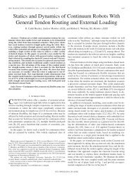
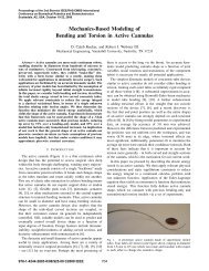
For full circumferential welds, the eccentricity of the experimental setup, shown<br />
in Figure 104, is approximately 0.02”. This level of eccentricity results in significant and<br />
unacceptable changes in the vertical position of the sphere surface relative to the tool, and<br />
thus unacceptable variations in weld depth. An in-process, force feedback control<br />
algorithm was therefore employed for the conical tool experiments as a means of<br />
maintaining a constant penetration depth around the entire sphere. The vertical position<br />
was adjusted based on torque signals received from a rotating cutting force dynamometer<br />
oriented in series with the tool. For the conical type tools it was found that desired<br />
position was better maintained if torque, rather than force, was used as the input in the<br />
decision making algorithm. An auto-zeroing procedure is performed over the start of the<br />
weld to determine the height of the material surface here relative to the tool. The tool is<br />
then plunged to the assigned penetration depth and the weld traverse is started. After 1”<br />
of weld traverse the measured torque from the dynamometer is set as the desired torque<br />
and from this point forward this torque value is maintained by vertical adjustments of tool<br />
position using the weld machine's vertical axis motor. Figure 123 in a later section shows<br />
the weld torque increasing with penetration depth at the 1000rpm, 10ipm parameter<br />
setting. The relationship between weld depth and process forces will be discussed later.<br />
Figure 105 and Figure 106 below demonstrate the torque control process for two welds<br />
runs(1000rpm, 10.4ipm, 0.095” weld depth). In the upper frame the axial force (blue)<br />
and desired axial force (green) are shown. The desired axial force is not used in the<br />
control algorithm and is shown for comparison with the measured axial force and the<br />
torque panel below. Torque was found to be a more reliable indicator of depth. These<br />
relationships are discussed later. The middle panels in Figure 105 and Figure 106 show<br />
the measured torque (blue) and desired torque (green). It can be seen in the figures that<br />
the desired torque, set after 1” of weld traverse, is followed closely. The bottom panel of<br />
the two figures is the vertical position of the tool relative to the height of the material<br />
surface at the weld plunge site (weld start). A linear encoder is used to track movements<br />
relative to this initial calibration. In this manner the vertical adjustments made by the tool<br />
to maintain the desired torque can be seen. As torque is highly sensitive to plunge depth<br />
and a constant torque is closely maintained throughout the weld traverse, it can be<br />
concluded that tool penetration depth is closely maintained throughout the weld traverse.<br />
118