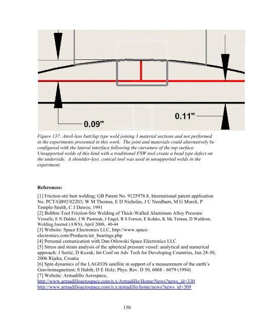
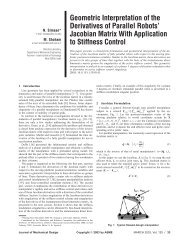
Figure 137: Anvil-less butt/lap type weld joining 3 material sections and not performed in the experiments presented in this work. The joint and materials could alternatively be configured with the lateral interface following the curvature of the top surface. Unsupported welds of this kind with a traditional FSW tool create a bead type defect on the underside. A shoulder-less, conical tool was used in unsupported welds in the experiment. References: [1] Friction-stir butt welding; GB Patent No. 9125978.8, International patent application No. PCT/GB92/02203; W M Thomas, E D Nicholas, J C Needham, M G Murch, P Temple-Smith, C J Dawes; 1991 [2] Bobbin-Tool Friction-Stir Welding of Thick-Walled Aluminum Alloy Pressure Vessels; E N Dalder, J W Pastrnak, J Engel, R S Forrest, E Kokko, K Mc Ternan, D Waldron; Welding Journal (AWS), April 2008, 40-44 [3] Website: Space Electronics LLC, http://www.spaceelectronics.com/Products/air_bearings.php [4] Personal comunication with Dan Otlowski Space Electronics LLC [5] Stress and strain analysis of the spherical pressure vessel: analytical and numerical approach: J Sertić, D Kozak; Int Conf on Adv Tech for Developing Countries, Jun 28-30, 2006 Rijeka, Croatia [6] Spin dynamics of the LAGEOS satellite in support of a measurement of the earth’s Gravitomagnetism; S Habib, D E Holz; Phys. Rev. D 50, 6068 - 6079 (1994) [7] Website: Armadillo Aerospace, http://www.armadilloaerospace.com/n.x/Armadillo/Home/News?news_id=330 http://www.armadilloaerospace.com/n.x/armadillo/home/news?news_id=309 150
[8] Metallurgical analysis of ablated aluminum alloy hemispheres; G J Fischer, R Maciag ; Internal Report, Polytechnic Inst of Brooklyn NY, Jul 1962 [9] Numerical analysis of the nonlinear deformation of a spherical pressure vessel made of laminated glass-plastic; Y M Grigorenko, A T Vasilenko, N N Kryukov, and T V Krizhanovskaya; Prikladnaya Mekhanika, Vol. 23, No ii, pp. 27-32, November, 1987 [10] Experimental study of shape imperfections and the load-carrying capacity of hemispherical glass shells; P F Zolotarev; Problemy Prochnosti, No. I0, pp. 91-95, October, 1981 [11] Cryoformed stainless steel pressure vessels for space applications; A Faure, L Gourgeon; Proc Eur Conf on Spacecraft Struc, Mat and Mech Testing, Braunschweig Germany, 4-6 Nov 1998 [12] Estimating the carrying capacity of spherical vessels from dynamic loading data; I V Belinskii, E I Zharkov, N A Zvonarev; Fizika Goreniya i Vzryva, Vol. 28, No. 5, pp. 117- 119, Sep-Oct, 1992 [13] Elastic analysis for thick cylinders and spherical pressure vessels made of functionally graded materials; Y.Z. Chen, X.Y. Lin; Comp Mat Sci, 44 (2008) 581– 587 [14] A study on failure characteristic of spherical pressure vessel; H S Lee, J H Yoon, J S Park, Y M Yi; Journal of Mat Processing Tech 164–165 (2005) 882–888 [15] Study on spherical pressure vessel of ceramics for deep-sea buoyancy module applications; Y Yano, S Takagawa; Japan Agency for Marine-Earth Science and Technology (JAMSTEC); Oceans 2004 MTS, 1554- 1559 Vol.3 [16] Design and development of an aluminum lined composite overwrapped spherical pressure vessel; R Veys, A Cederberg, D B Tiller; Brunswick Corporation, Defense Division, Lincoln Nb, Internal Report AIAA-89-2642, 1989 [17] Design and development of a carbon overwrapped aluminum lined spherical pressurant tank; D B Tiller, C F Murray, R B Veys; Brunswick Corporation, Defense Division, Lincoln Nb, Internal Report, 1990 [18] Behavior and ultimate tensile strength of partial penetration groove welds; D P Gagnon, D J Kennedy, 1987 [19] Evaluation and tensile strength of partial penetration butt welded joints by ultrasonic testing; H Matsuura, A Kaji; Jpn Soc Mech Eng , Vol 66, No 647, A, 1419-1424, 2000 [20] The Effect of Mismatch on the Collapse Strength of Machined Hemispherical Shells; M G Costello; Naval Ship Research and Development Center, Washington DC, Internal Report Ad0874760, 1970 [21] A new, highly efficient deep water ROV buoyancy system; E M Patton, T S Rennick; Offshore Technology Conference, 3 May-6 May 1999, Houston Tx [22] Partial-penetration welded connections for aluminum compression members; J H Jennison, R S Gill; Naval Ordinance Test Station, China Lake Ca, Internal Report AD0602361, 1964 [23] Method of friction stir welding and retractable shoulderless variable penetration friction stir welding tool; US Patent #7,234,626; T Trapp, J Fischer, J Bernath; Edison Welding Institute (EWI), 2007 [24] Retractable shoulderless variable penetration friction stir welding tool; US Patent #7,404,510; T Trapp, J Fischer, J Bernath; Edison Welding Institute (EWI), 2007 151
- Page 1 and 2:
FRICTION STIR WELDING OF SPHERES, C
- Page 3 and 4:
TABLE OF CONTENTS TABLE OF FIGURES
- Page 5 and 6:
Appendix ..........................
- Page 7 and 8:
Figure 16: Left(FE streamline), Mid
- Page 9 and 10:
Figure 51: A thermal camera image t
- Page 11 and 12:
for a similar conventional weld (3/
- Page 13 and 14:
Figure 102: Tapered retraction proc
- Page 15 and 16:
setting are indicated. Note that st
- Page 17 and 18:
Unsupported welds of this kind with
- Page 19 and 20:
Figure 157: A thermal camera image
- Page 21 and 22:
ottom sample is a tungsten inert ga
- Page 23 and 24:
N - newton (force unit) n - visco-p
- Page 25 and 26:
INTRODUCTION Friction Stir Welding,
- Page 27 and 28:
educed conduction lengths. In small
- Page 29 and 30:
CHAPTER I LITERATURE REVIEW: COMPUT
- Page 31 and 32:
frictional condition at the interfa
- Page 33 and 34:
contact. The contact area can inclu
- Page 35 and 36:
For horizontal sections, a heat inp
- Page 37 and 38:
(1.11) where r p is the probe (pin)
- Page 39 and 40:
This efficiency term, η pd , is kn
- Page 41 and 42:
The heat input on the tool surface
- Page 43 and 44:
The added complication of these met
- Page 45 and 46:
Figure 5: Lateral cross sections of
- Page 47 and 48:
Flow stress in aluminum alloys is d
- Page 49 and 50:
Figure 8: Three flow fields a) rota
- Page 51 and 52:
and post-weld cool-down. This model
- Page 53 and 54:
Williams et al. [60] use a 2D-axisy
- Page 55 and 56:
Figure 16: Left(FE streamline), Mid
- Page 57 and 58:
Figure 18: Temperature contour over
- Page 59 and 60:
Figure 22: Temperature distribution
- Page 61 and 62:
Figure 24: Lateral velocity contour
- Page 63 and 64:
Figure 26: Experimental(white) vers
- Page 65 and 66:
Figure 28: Top view schematic of tu
- Page 67 and 68:
[5] Taylor RE, Groot H, Goerz T, Fe
- Page 69 and 70:
[41] Heinz B., Skrotzki B., Eggler
- Page 71 and 72:
CHAPTER II COMPUTATIONAL ANALYSIS O
- Page 73 and 74:
Figure 30: Blind t-joint setup with
- Page 75 and 76:
Figure 33: Process forces and later
- Page 77 and 78:
Figure 35: Experimental Welds, Axia
- Page 79 and 80:
Figure 37: FEA boundary conditions
- Page 81 and 82:
A 4500 N axial force is applied eve
- Page 83 and 84:
axial force with lateral offset dur
- Page 85 and 86:
Figure 42: Contour plot of von Mise
- Page 87 and 88:
Figure 44: Deformation contour for
- Page 89 and 90:
Figure 46: Quarter-plate model for
- Page 91 and 92:
Figure 49: Contour plot of deflecti
- Page 93 and 94:
where P is the weld power (W), Q is
- Page 95 and 96:
Figure 52: Fluent CFD model zones.
- Page 97 and 98:
Figure 55: Thermal contour of weld
- Page 99 and 100:
Figure 59: Thermal contour of weld
- Page 101 and 102:
Figure 61: Velocity vectors for 0.0
- Page 103 and 104:
Figure 65: Contour of velocity magn
- Page 105 and 106:
CHAPTER III THE APPLICATION OF SHOU
- Page 107 and 108:
Figure 66: A shoulder-less, conical
- Page 109 and 110:
Figure 68: Typical axial(Z-axis) fo
- Page 111 and 112:
Figure 71: 90° conical tool macros
- Page 113 and 114:
Figure 75: Run 3, 80° conical tool
- Page 115 and 116:
Figure 79: (90º tool) Ultimate ten
- Page 117 and 118:
Figure 83: (90º tool) Lateral forc
- Page 119 and 120:
Figure 87: (80º tool) Lateral forc
- Page 121 and 122:
The Eulerian, finite volume, CFD so
- Page 123 and 124: Figure 92 shows the increasing elem
- Page 125 and 126: Figure 91: CFD model geometry consi
- Page 127 and 128: Figure 95: Lateral cross-section of
- Page 129 and 130: Figure 96: Attempts a probe tapered
- Page 131 and 132: CHAPTER IV THE FRICTION STIR WELDIN
- Page 133 and 134: applications for its high strength
- Page 135 and 136: Figure 97: Experimental weld sample
- Page 137 and 138: Figure 99: Split protrusion type de
- Page 139 and 140: with a cupped recess. It is however
- Page 141 and 142: of tapered retraction (i.e. move th
- Page 143 and 144: The adjustments in vertical positio
- Page 145 and 146: manners the assigned depth was main
- Page 147 and 148: Figure 108: Lateral macrosections f
- Page 149 and 150: Figure 110: (Supported, cupped tool
- Page 151 and 152: Figure 112: (Supported, cupped tool
- Page 153 and 154: Figure 114: (Supported, cupped tool
- Page 155 and 156: apparent strength of 26% parent whi
- Page 157 and 158: with a 100º conical tool (0.025”
- Page 159 and 160: Figure 119: Macrosection view of an
- Page 161 and 162: and tooling. Torque is highly depen
- Page 163 and 164: locally in proportion to the local
- Page 165 and 166: Figure 126: (threaded tool) Contour
- Page 167 and 168: Figure 128: (conical tool) Geometry
- Page 169 and 170: Figure 131: (threaded tool) Lateral
- Page 171 and 172: The results presented here show tha
- Page 173: Figure 136:(from left: Tapered retr
- Page 177 and 178: CHAPTER V FRICTION STIR WELDING OF
- Page 179 and 180: Collaboration between Advanced Meta
- Page 181 and 182: eccentricity, the method of interio
- Page 183 and 184: gas tungsten arc welding of small d
- Page 185 and 186: Full penetration welds of 4.2” (1
- Page 187 and 188: Figure 143: The curvature of the pi
- Page 189 and 190: Figure 144: Experimental axial forc
- Page 191 and 192: Together, a fine wall thickness tol
- Page 193 and 194: Figure 147: Axial force history for
- Page 195 and 196: The weld macrosections show complet
- Page 197 and 198: Figure 154: Macrosections of welds
- Page 199 and 200: Figure 157: A thermal camera image
- Page 201 and 202: Figure 159: Average tool shank temp
- Page 203 and 204: 471,146 faces. The meshes are fine
- Page 205 and 206: Figure 162: A closeup view of mesh
- Page 207 and 208: 4 2 3 4 5 16 " 1.745 2 0.24
- Page 209 and 210: applied heat locally in proportion
- Page 211 and 212: Figure 164: Modeled temperature con
- Page 213 and 214: Figure 167: Modeled temperature con
- Page 215 and 216: Figure 169: Modeled temperature con
- Page 217 and 218: Figure 172: Model pathlines for the
- Page 219 and 220: Figure 174: Model pathlines for the
- Page 221 and 222: later speed setting, the tool welds
- Page 223 and 224: Figure 178: Zoom view of a macro ta
- Page 225 and 226:
Figure 180: The superficial appeara
- Page 227 and 228:
Figure 182: The rotary welding appa
- Page 229 and 230:
Figure 185: A diagram illustrating
- Page 231 and 232:
CONCLUSION AND FUTURE WORK Conclusi
- Page 233 and 234:
new FSW process environment is reso