D.H. Lammlein PhD Dissertation - Vanderbilt University
D.H. Lammlein PhD Dissertation - Vanderbilt University
D.H. Lammlein PhD Dissertation - Vanderbilt University
You also want an ePaper? Increase the reach of your titles
YUMPU automatically turns print PDFs into web optimized ePapers that Google loves.
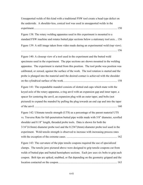
Unsupported welds of this kind with a traditional FSW tool create a bead type defect on<br />
the underside. A shoulder-less, conical tool was used in unsupported welds in the<br />
experiment....................................................................................................................... 150<br />
Figure 138: The rotary welding apparatus used in this experiment is mounted to a<br />
standard FSW machine and rotates butted pipe sections below a stationary tool axis. .. 156<br />
Figure 139: A still image taken from video made during an experimental weld (top view).<br />
......................................................................................................................................... 156<br />
Figure 140: A closeup view of a tool used in the experiment and the butted weld<br />
specimens used in the experiment. The pipe sections are shown mounted in the welding<br />
apparatus. The experiment is started from this position. The tool probe was position was<br />
calibrated, or zeroed, against the surface of the work. The tool rotation is started and the<br />
probe is plunged into the material until the desired contact is achieved with the shoulder<br />
on the cylindrical surface of the work............................................................................. 158<br />
Figure 141: The expandable mandrel consists of slotted end caps which mate with the<br />
keyed axle of the rotary apparatus, a ring anvil with an expansion gap and inner taper, a<br />
spacer for centering the anvil, an expansion plug with an outer taper, and bolts (not<br />
pictured) to expand the mandrel by pulling the plug towards an end cap and into the taper<br />
of the anvil. ..................................................................................................................... 160<br />
Figure 142: Ultimate tensile strength (UTS) as a percentage of the parent material UTS<br />
vs. Traverse Rate for full-penetration butted pipe welds made with 5/8” diameter, scrolled<br />
shoulder and 0.18” length, threaded probe tools. Data is shown for both the<br />
3/16”(4.8mm) diameter probe tool and the 0.236”(6mm) diameter probe tool used in the<br />
experiment. Weld tensile strength is observed to increase with increasing process rates<br />
with the exception of the extreme cases. ........................................................................ 162<br />
Figure 143: The curvature of the pipe tensile coupons required the use of specialized<br />
clamps. The tensile jaws pictured above were designed to grip tensile coupons cut from<br />
welds of butted pipe and butted hemisphere sections. Each jaw uses six bolts to grip each<br />
coupon. Bolt tips are spiked, snubbed, or flat depending on the geometry gripped and the<br />
location contacted on the coupon. ................................................................................... 163<br />
xvii


