D.H. Lammlein PhD Dissertation - Vanderbilt University
D.H. Lammlein PhD Dissertation - Vanderbilt University
D.H. Lammlein PhD Dissertation - Vanderbilt University

Create successful ePaper yourself
Turn your PDF publications into a flip-book with our unique Google optimized e-Paper software.
Figure 51: A thermal camera image taken during the steady state weld period of a<br />
1000rpm, 4 ipm, blind-T weld .......................................................................................... 70<br />
Figure 52: Fluent CFD model zones. ................................................................................ 71<br />
Figure 53: Surface heat fluxes for CFD model faces. ....................................................... 71<br />
Figure 54: Thermal contour for laterally centered case. ................................................... 72<br />
Figure 55: Thermal contour of weld material at the interface for laterally centered case. 73<br />
Figure 56: Thermal contour for 0.05in advancing side lateral offset case........................ 73<br />
Figure 57: Thermal contour of weld material at the interface for 0.05in advancing side<br />
lateral offset case............................................................................................................... 74<br />
Figure 58: Thermal contour for 0.05in retreating side lateral offset case. ........................ 74<br />
Figure 59: Thermal contour of weld material at the interface for 0.05in retreating side<br />
lateral offset case............................................................................................................... 75<br />
Figure 60: Contour of total pressure for 0.05” advancing side offset case. ...................... 76<br />
Figure 61: Velocity vectors for 0.05” advancing side offset case. ................................... 77<br />
Figure 62: Contour of velocity magnitude for 0.05” advancing side offset case. ............ 77<br />
Figure 63: Contour of total pressure for 0.05” retreating side offset case. ....................... 78<br />
Figure 64: Velocity vectors for 0.05” retreating side offset case. .................................... 78<br />
Figure 65: Contour of velocity magnitude for 0.05” retreating side offset case. .............. 79<br />
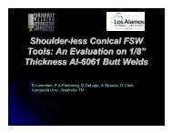
Figure 66: A shoulder-less, conical tool (90º inclusive angle) used in the experiment .... 83<br />
Figure 67: XY plane force oscillations were typically present at low spindle head angles<br />
with conical welds, presumably due to the lack a horizontal, stabilizing shoulder. The<br />
experiment was therefore performed at a 4° angle where this problem did not exist. ...... 84<br />
Figure 68: Typical axial(Z-axis) force data. ..................................................................... 85<br />
Figure 69: Typical in plane force data. ............................................................................. 85<br />
Figure 70: Typical surface appearance for 90° conical tool welds on 1/8” thick butted<br />
6061 alloy aluminum plates. Typical conical surface defects are pointed out. ................ 86<br />
ix