- Page 1 and 2:
FRICTION STIR WELDING OF SPHERES, C
- Page 3 and 4:
TABLE OF CONTENTS TABLE OF FIGURES
- Page 5 and 6:
Appendix ..........................
- Page 7 and 8:
Figure 16: Left(FE streamline), Mid
- Page 9 and 10:
Figure 51: A thermal camera image t
- Page 11 and 12:
for a similar conventional weld (3/
- Page 13 and 14:
Figure 102: Tapered retraction proc
- Page 15 and 16:
setting are indicated. Note that st
- Page 17 and 18:
Unsupported welds of this kind with
- Page 19 and 20:
Figure 157: A thermal camera image
- Page 21 and 22:
ottom sample is a tungsten inert ga
- Page 23 and 24:
N - newton (force unit) n - visco-p
- Page 25 and 26:
INTRODUCTION Friction Stir Welding,
- Page 27 and 28:
educed conduction lengths. In small
- Page 29 and 30:
CHAPTER I LITERATURE REVIEW: COMPUT
- Page 31 and 32:
frictional condition at the interfa
- Page 33 and 34:
contact. The contact area can inclu
- Page 35 and 36:
For horizontal sections, a heat inp
- Page 37 and 38:
(1.11) where r p is the probe (pin)
- Page 39 and 40:
This efficiency term, η pd , is kn
- Page 41 and 42:
The heat input on the tool surface
- Page 43 and 44:
The added complication of these met
- Page 45 and 46:
Figure 5: Lateral cross sections of
- Page 47 and 48:
Flow stress in aluminum alloys is d
- Page 49 and 50:
Figure 8: Three flow fields a) rota
- Page 51 and 52:
and post-weld cool-down. This model
- Page 53 and 54:
Williams et al. [60] use a 2D-axisy
- Page 55 and 56:
Figure 16: Left(FE streamline), Mid
- Page 57 and 58:
Figure 18: Temperature contour over
- Page 59 and 60:
Figure 22: Temperature distribution
- Page 61 and 62:
Figure 24: Lateral velocity contour
- Page 63 and 64:
Figure 26: Experimental(white) vers
- Page 65 and 66:
Figure 28: Top view schematic of tu
- Page 67 and 68:
[5] Taylor RE, Groot H, Goerz T, Fe
- Page 69 and 70:
[41] Heinz B., Skrotzki B., Eggler
- Page 71 and 72:
CHAPTER II COMPUTATIONAL ANALYSIS O
- Page 73 and 74:
Figure 30: Blind t-joint setup with
- Page 75 and 76:
Figure 33: Process forces and later
- Page 77 and 78:
Figure 35: Experimental Welds, Axia
- Page 79 and 80:
Figure 37: FEA boundary conditions
- Page 81 and 82:
A 4500 N axial force is applied eve
- Page 83 and 84:
axial force with lateral offset dur
- Page 85 and 86:
Figure 42: Contour plot of von Mise
- Page 87 and 88:
Figure 44: Deformation contour for
- Page 89 and 90:
Figure 46: Quarter-plate model for
- Page 91 and 92:
Figure 49: Contour plot of deflecti
- Page 93 and 94:
where P is the weld power (W), Q is
- Page 95 and 96:
Figure 52: Fluent CFD model zones.
- Page 97 and 98:
Figure 55: Thermal contour of weld
- Page 99 and 100:
Figure 59: Thermal contour of weld
- Page 101 and 102:
Figure 61: Velocity vectors for 0.0
- Page 103 and 104:
Figure 65: Contour of velocity magn
- Page 105 and 106:
CHAPTER III THE APPLICATION OF SHOU
- Page 107 and 108:
Figure 66: A shoulder-less, conical
- Page 109 and 110:
Figure 68: Typical axial(Z-axis) fo
- Page 111 and 112:
Figure 71: 90° conical tool macros
- Page 113 and 114:
Figure 75: Run 3, 80° conical tool
- Page 115 and 116:
Figure 79: (90º tool) Ultimate ten
- Page 117 and 118:
Figure 83: (90º tool) Lateral forc
- Page 119 and 120:
Figure 87: (80º tool) Lateral forc
- Page 121 and 122:
The Eulerian, finite volume, CFD so
- Page 123 and 124:
Figure 92 shows the increasing elem
- Page 125 and 126:
Figure 91: CFD model geometry consi
- Page 127 and 128:
Figure 95: Lateral cross-section of
- Page 129 and 130:
Figure 96: Attempts a probe tapered
- Page 131 and 132:
CHAPTER IV THE FRICTION STIR WELDIN
- Page 133 and 134:
applications for its high strength
- Page 135 and 136:
Figure 97: Experimental weld sample
- Page 137 and 138:
Figure 99: Split protrusion type de
- Page 139 and 140:
with a cupped recess. It is however
- Page 141 and 142:
of tapered retraction (i.e. move th
- Page 143 and 144:
The adjustments in vertical positio
- Page 145 and 146:
manners the assigned depth was main
- Page 147 and 148:
Figure 108: Lateral macrosections f
- Page 149 and 150:
Figure 110: (Supported, cupped tool
- Page 151 and 152:
Figure 112: (Supported, cupped tool
- Page 153 and 154:
Figure 114: (Supported, cupped tool
- Page 155 and 156: apparent strength of 26% parent whi
- Page 157 and 158: with a 100º conical tool (0.025”
- Page 159 and 160: Figure 119: Macrosection view of an
- Page 161 and 162: and tooling. Torque is highly depen
- Page 163 and 164: locally in proportion to the local
- Page 165 and 166: Figure 126: (threaded tool) Contour
- Page 167 and 168: Figure 128: (conical tool) Geometry
- Page 169 and 170: Figure 131: (threaded tool) Lateral
- Page 171 and 172: The results presented here show tha
- Page 173 and 174: Figure 136:(from left: Tapered retr
- Page 175 and 176: [8] Metallurgical analysis of ablat
- Page 177 and 178: CHAPTER V FRICTION STIR WELDING OF
- Page 179 and 180: Collaboration between Advanced Meta
- Page 181 and 182: eccentricity, the method of interio
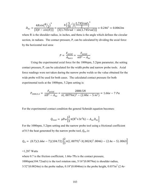
- Page 183 and 184: gas tungsten arc welding of small d
- Page 185 and 186: Full penetration welds of 4.2” (1
- Page 187 and 188: Figure 143: The curvature of the pi
- Page 189 and 190: Figure 144: Experimental axial forc
- Page 191 and 192: Together, a fine wall thickness tol
- Page 193 and 194: Figure 147: Axial force history for
- Page 195 and 196: The weld macrosections show complet
- Page 197 and 198: Figure 154: Macrosections of welds
- Page 199 and 200: Figure 157: A thermal camera image
- Page 201 and 202: Figure 159: Average tool shank temp
- Page 203 and 204: 471,146 faces. The meshes are fine
- Page 205: Figure 162: A closeup view of mesh
- Page 209 and 210: applied heat locally in proportion
- Page 211 and 212: Figure 164: Modeled temperature con
- Page 213 and 214: Figure 167: Modeled temperature con
- Page 215 and 216: Figure 169: Modeled temperature con
- Page 217 and 218: Figure 172: Model pathlines for the
- Page 219 and 220: Figure 174: Model pathlines for the
- Page 221 and 222: later speed setting, the tool welds
- Page 223 and 224: Figure 178: Zoom view of a macro ta
- Page 225 and 226: Figure 180: The superficial appeara
- Page 227 and 228: Figure 182: The rotary welding appa
- Page 229 and 230: Figure 185: A diagram illustrating
- Page 231 and 232: CONCLUSION AND FUTURE WORK Conclusi
- Page 233 and 234: new FSW process environment is reso