FIRE DESIGN OF STEEL MEMBERS - Civil and Natural Resources ...
FIRE DESIGN OF STEEL MEMBERS - Civil and Natural Resources ...
FIRE DESIGN OF STEEL MEMBERS - Civil and Natural Resources ...

You also want an ePaper? Increase the reach of your titles
YUMPU automatically turns print PDFs into web optimized ePapers that Google loves.
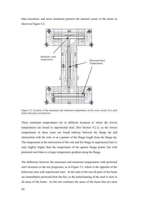
than elsewhere, <strong>and</strong> more insulation protects the internal corner of the beam as<br />
shown in Figure 5.2:<br />
Minimum steel<br />
temperatures<br />
Maximum Steel<br />
Temperatures<br />
Figure 5.2: Location of the maximum <strong>and</strong> minimum temperatures on the cross section of a steel<br />
beam with spray on protection<br />
These minimum temperatures are in different locations to where the lowest<br />
temperatures are found in unprotected steel, (See Section 4.2.1), as the lowest<br />
temperatures in these cases are found midway between the flange tip <strong>and</strong><br />
intersection with the web, or at a quarter of the flange length from the flange tip.<br />
The temperature at the intersection of the web <strong>and</strong> the flange in unprotected steel is<br />
only slightly higher than the temperature of the quarter flange points, but with<br />
protected steel there is a larger temperature gradient along the flange.<br />
The difference between the maximum <strong>and</strong> minimum temperatures with protected<br />
steel increases as the test progresses, as in Figure 5.1, which is the opposite of the<br />
behaviour seen with unprotected steel. At the start of the test all parts of the beam<br />
are immediately protected from the fire, so the initial heating of the steel is slow in<br />
all areas of the beam. As the test continues the areas of the beam that are most<br />
84