- Page 1 and 2:
TECH - SPEC’S Technician’s Pock
- Page 3 and 4:
Component Checks PAGE Control Board
- Page 5 and 6:
UNIT TYPE HOSHIZAKI MODEL NUMBER ID
- Page 7 and 8:
REGISTRATION- WARRANTY INFORMATION
- Page 9 and 10:
Hoshizaki recommends that the ice m
- Page 11 and 12:
Note: All Electrical connections mu
- Page 13 and 14:
13 12/01/02 2/20/03
- Page 15 and 16:
SYSTEM CHARGE - R-404A The ice mach
- Page 17 and 18:
R-404A URC REMOTE CONDENSERS (Conde
- Page 19 and 20:
“E” Control Board Adjustment Ch
- Page 21 and 22:
“E” Control Board Functions An
- Page 23 and 24:
MANUAL RESET SAFETIES: The Alpine c
- Page 25 and 26:
COMPRESSOR DATA (Ohms) (Ohms) OIL C
- Page 27 and 28:
REMOTE HEAD PRESSURE CONTROL All re
- Page 29 and 30:
acket. When installing, make sure t
- Page 31 and 32:
inch of the sensor. It also connect
- Page 33 and 34:
4. Harvest Pump Out When the float
- Page 35 and 36:
KM CHECK OUT PROCEDURE The followin
- Page 37 and 38:
RESERVOIR FLUSH SYSTEM A displaceme
- Page 39 and 40:
(Fuse Label) CONTROL FUSE (10A) If
- Page 41 and 42:
UNIVERSAL REPLACEMENT FLOAT SWITCH:
- Page 43 and 44:
2. Turn the control switch to ICE a
- Page 45 and 46:
closes a magnetic proximity switch.
- Page 47 and 48:
The sensor has two LED lamps that l
- Page 49 and 50:
LARGER STYLE KM’s 1 2 3 4 5 6 7 8
- Page 51 and 52: Because of the different flow rates
- Page 53 and 54: 3. Bridging or ice strips a) Bridgi
- Page 55 and 56: PLEASE COMPLETE WHEN DIAGNOSING A F
- Page 57 and 58: PREVENTATIVE MAINTENENCE: Perventat
- Page 59 and 60: RECOMMENDED SANITIZING SOLUTION MIX
- Page 61 and 62: KM-150BAF, BWF KM-150BAF-E, BWF-E 6
- Page 63 and 64: KML-250MAF/H, KML-250MWF/H KML-350M
- Page 65 and 66: KM-500MAF/H, KM-500MWF/H KM-500MAF/
- Page 67 and 68: KM-1300SAF/H, SAF/H-E KM-1300SWF/H,
- Page 69 and 70: KM-1300MAF/H, MWF/H 69 12/01/02 12/
- Page 71 and 72: KM-1800SAH, SAH3 KM-2000SWF/H, KM-2
- Page 73 and 74: R-404A PERFORMANCE DATA MODEL: KM-1
- Page 75 and 76: PERFORMANCE DATA MODEL: KM-250BM_F
- Page 77 and 78: MODEL: KM-280M_F-E & KM-280MAH-E Su
- Page 79 and 80: R-404A PERFORMANCE DATA MODEL: KML-
- Page 81 and 82: MODEL: KML-450M_F & H *MWH with SN
- Page 83 and 84: PERFORMANCE DATA MODEL: KM-500M_F &
- Page 85 and 86: PERFORMANCE DATA MODEL: KM-500MAF-E
- Page 87 and 88: PERFORMANCE DATA MODEL: KM-630M_F &
- Page 89 and 90: PERFORMANCE DATA MODEL: KM-630M_F-E
- Page 91 and 92: R-404A PERFORMANCE DATA MODEL: KM-9
- Page 93 and 94: PERFORMANCE DATA MODEL: KM-1300S_F
- Page 95 and 96: MODEL: KM-1300NRF & H Supply Voltag
- Page 97 and 98: 1200 1106 988 26 29 35 240 268 287
- Page 99 and 100: PERFORMANCE DATA MODEL: KM-1600MRF3
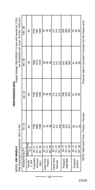
- Page 101: 50 / 9 70 / 21 90 / 32 R-404A PERFO
- Page 105 and 106: PERFORMANCE DATA MODEL: KM-2400SRF3
- Page 107 and 108: Model Wiring Diagram Page KM Wiring
- Page 109 and 110: Wiring Diagram Model Page KM Wiring
- Page 111 and 112: 115 VAC 24 VDC CAPACITIVE PROXIMITY
- Page 113 and 114: B KM-150BAF-E, BWF-E Note: Fuse was
- Page 115 and 116: D KM-280 MAF-E/H-E, MWF-E/H-E Notes
- Page 117 and 118: F KML-350MAF/H, MWF/H Notes: 1.Some
- Page 119 and 120: H KM-500 MAF/H, MWF/H Notes: 1.Some
- Page 121 and 122: J KM-500 MAF-E Notes: 1.Some H seri
- Page 123 and 124: L KM-630 MAF/H, MWF/H Notes: 1.Some
- Page 125 and 126: N KM-630 MAF-E/H-E, MWF-E/H-E Notes
- Page 127 and 128: P KM-900 MRF/H Notes: 1.Some H seri
- Page 129 and 130: R KM-1300 SAF/H, SWF/H KM-1300 MAF/
- Page 131 and 132: T KM-1300 SAF3/H3, SWF3/H3 Note: 1.
- Page 133 and 134: V KM-1300 SAF-E, SWF-E Note: 1. Fus
- Page 135 and 136: X KM-1300 NRF / H 135 12/01/02 12/2
- Page 137 and 138: Z KM-1600SWF3/H3, SRF3/H3 KM-1600MR
- Page 139 and 140: BB KM-1800 SAH3 Note: 1. Fuse was a
- Page 141 and 142: FLAKER/DCM INSTALLATION - GENERAL A
- Page 143 and 144: COMPONENT TECHNICAL DATA CONTROL TR
- Page 145 and 146: Although it is common practice to i
- Page 147 and 148: AUGER INSPECTION / BEARING REPLACEM
- Page 149 and 150: is included in the motor windings.
- Page 151 and 152: FLAKER WATER FILL SYSTEM The reserv
- Page 153 and 154:
Flaker Sequence of Operation The Ho
- Page 155 and 156:
FLAKER PERIODIC FLUSH Beginning wit
- Page 157 and 158:
WATER AND REFRIGERATION CIRCUIT DRA
- Page 159 and 160:
B F-450 MAF/H F-500 BAF 159 12/01/0
- Page 161 and 162:
D F-1000 MRF F-1001 MRH 161 12/01/0
- Page 163 and 164:
F F-2000 MRF F-2000 MRH 163 12/01/0
- Page 165 and 166:
H DCM-240 BAF DCM-270 BAH 165 12/01
- Page 167 and 168:
R-404A PERFORMANCE DATA MODEL: F-30
- Page 169 and 170:
MODEL: F-500BAF & BAF -C (cubelet)
- Page 171 and 172:
MODEL: F-800M _F-C / H-C (cubelet)
- Page 173 and 174:
R-404A PERFORMANCE DATA MODEL: F- 1
- Page 175 and 176:
R-22 “ SPECIAL MODEL” PERFORMAN
- Page 177 and 178:
R-404A PERFORMANCE DATA MODEL: F- 1
- Page 179 and 180:
Kg=lbs. x .454 Production 24 hours
- Page 181 and 182:
MODEL: F-2000M_F-C/H-C (cubelet) Su
- Page 183 and 184:
MODEL: F-2000MLF/H & MLF-C/H-C (cub
- Page 185 and 186:
R-404A PERFORMANCE DATA MODEL: DCM-
- Page 187 and 188:
R-404A PERFORMANCE DATA MODEL: DCM-
- Page 189 and 190:
Model Number DCM/Flaker Wiring Diag
- Page 191 and 192:
(B) DCM-270 BAH 191 12/01/02 12/20/
- Page 193 and 194:
(D) DCM-500 BAF, BWF Serial numbers
- Page 195 and 196:
(F) DCM-750 BAF, BWF Serial numbers
- Page 197 and 198:
(H) DCM-750 BAH, BWH 197 12/01/02 1
- Page 199 and 200:
(J) F-450 MAF/H 199 12/01/02 12/20/
- Page 201 and 202:
(L) F-500 BAF 201 12/20/03 12/01/02
- Page 203 and 204:
(N) F-1000 MAF, MWF, MRF 203 12/01/
- Page 205 and 206:
(P) F-1000 MAF-50 205 12/01/02 12/2
- Page 207 and 208:
(R) F-1001 MAH, MWH, MRH 207 12/01/
- Page 209 and 210:
(T) F-2000 MRF/H, MWF/H 209 12/01/0
- Page 211 and 212:
(V) F-2000 MLF/H 211 12/01/02 12/20
- Page 213 and 214:
NOTES 213 12/01/02 12/20/03 2/20/03