TECH - SPEC'S Technician's Pocket Guide - Hoshizaki America, Inc.
TECH - SPEC'S Technician's Pocket Guide - Hoshizaki America, Inc.
TECH - SPEC'S Technician's Pocket Guide - Hoshizaki America, Inc.
You also want an ePaper? Increase the reach of your titles
YUMPU automatically turns print PDFs into web optimized ePapers that Google loves.
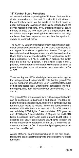
“E” Control Board Functions<br />
An instruction label explaining the “E” board features is included<br />
somewhere on the unit. You should find it either on<br />
the control box cover, on the inside of the front panel, or<br />
under the top panel. A stick on label is also included with the<br />
service replacement board. If you are replacing an “E” board,<br />
be sure to place the new label over the original label. This<br />
will advise anyone performing future service that the original<br />
board has been replaced and explain the application<br />
switch as outlined below.<br />
{<br />
The #2A1410-02 universal replacement board has an application<br />
switch between relays X3 & X4 that is not included on<br />
the original factory board supplied with the unit. This application<br />
switch allows this replacement board to be used on older<br />
C and Alpine control board models. The application switch<br />
has 2 positions (C & ALP). On R-404A models, this switch<br />
must be in the ALP position. If the switch is left in the C<br />
position, the compressor contactor will energize as soon as<br />
power is supplied to the unit whether the power switch is ON<br />
or OFF.<br />
There are 4 green LED’s which light in sequence throughout<br />
the unit operation. It is important to note that the green LED’s<br />
are not numbered consecutively. LED1 is located at the edge<br />
of the board beside the K-2 transformer connection. The numbering<br />
sequence from the outside edge of the board is 1, 4, 3,<br />
and 2.<br />
The green LED’s are also used for a built-in output test which<br />
can be conducted to diagnose a bad board. The label explains<br />
the output test procedure. The correct lighting sequence<br />
for the output test is as follows. When the control switch is<br />
switched ON with the output test switch S-3 ON, after a 5<br />
second delay, LED2 lights. 5 seconds later LED2 goes out<br />
and LED3 lights. 5 seconds later LED3 goes out and LED4<br />
lights. 5 seconds later LED4 goes out and LED1 lights. 5<br />
seconds later LED1 goes out and LED4 lights to begin the<br />
normal sequence of operation. If the LED’s follow this sequence,<br />
the board is OK. If any other lighting sequence occurs,<br />
the board is bad.<br />
A copy of the “E” board label is included on the next page.<br />
Review the board label thoroughly to understand the “E” board<br />
functions.<br />
21<br />
12/01/02 12/20/03<br />
2/20/03


