TECH - SPEC'S Technician's Pocket Guide - Hoshizaki America, Inc.
TECH - SPEC'S Technician's Pocket Guide - Hoshizaki America, Inc.
TECH - SPEC'S Technician's Pocket Guide - Hoshizaki America, Inc.
You also want an ePaper? Increase the reach of your titles
YUMPU automatically turns print PDFs into web optimized ePapers that Google loves.
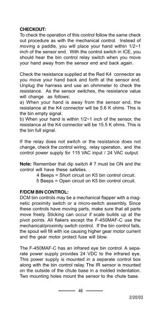
CHECKOUT:<br />
To check the operation of this control follow the same check<br />
out procedure as with the mechanical control. Instead of<br />
moving a paddle, you will place your hand within 1/2~1<br />
inch of the sensor end. With the control switch in ICE, you<br />
should hear the bin control relay switch when you move<br />
your hand away from the sensor end and back again.<br />
Check the resistance supplied at the Red K4 connector as<br />
you move your hand back and forth at the sensor end.<br />
Unplug the harness and use an ohmmeter to check the<br />
resistance. As the sensor switches, the resistance value<br />
will change as follows:<br />
a) When your hand is away from the sensor end, the<br />
resistance at the K4 connector will be 5.6 K ohms. This is<br />
the bin empty signal.<br />
b) When your hand is within 1/2~1 inch of the sensor, the<br />
resistance at the K4 connector will be 15.5 K ohms. This is<br />
the bin full signal.<br />
If the relay does not switch or the resistance does not<br />
change, check the control wiring, relay operation, and the<br />
control power supply for 115 VAC input / 24 VAC output.<br />
Note: Remember that dip switch # 7 must be ON and the<br />
control will have these safeties.<br />
4 Beeps = Short circuit on K5 bin control circuit.<br />
5 Beeps = Open circuit on K5 bin control circuit.<br />
F/DCM BIN CONTROL:<br />
DCM bin controls may be a mechanical flapper with a magnetic<br />
proximity switch or a micro-switch assembly. Since<br />
these controls have moving parts, make sure that all parts<br />
move freely. Sticking can occur if scale builds up at the<br />
pivot points. All flakers except the F-450MAF-C use the<br />
mechanical/proximity switch control. If the bin control fails,<br />
the spout will fill with ice causing higher gear motor current<br />
and the gear motor protect fuse will blow.<br />
The F-450MAF-C has an infrared eye bin control. A separate<br />
power supply provides 24 VDC to the infrared eye.<br />
This power supply is mounted in a separate control box<br />
along with the bin control relay. The IR sensor is mounted<br />
on the outside of the chute base in a molded indentation.<br />
Two mounting holes mount the sensor to the chute base.<br />
46<br />
12/01/02 12/20/03<br />
2/20/03


