

TECH - SPEC'S Technician's Pocket Guide - Hoshizaki America, Inc.
TECH - SPEC'S Technician's Pocket Guide - Hoshizaki America, Inc.
TECH - SPEC'S Technician's Pocket Guide - Hoshizaki America, Inc.

You also want an ePaper? Increase the reach of your titles
YUMPU automatically turns print PDFs into web optimized ePapers that Google loves.
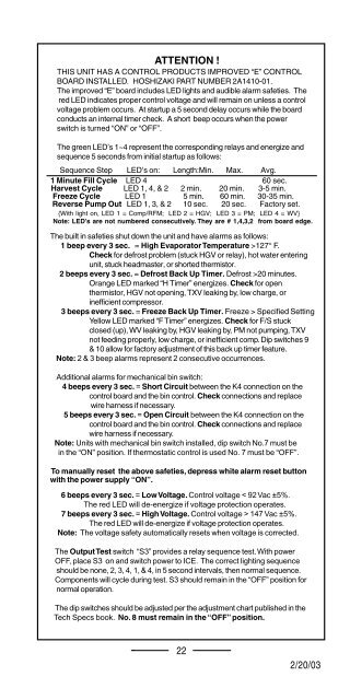
ATTENTION !<br />
THIS UNIT HAS A CONTROL PRODUCTS IMPROVED “E” CONTROL<br />
BOARD INSTALLED. HOSHIZAKI PART NUMBER 2A1410-01.<br />
The improved “E” board includes LED lights and audible alarm safeties. The<br />
red LED indicates proper control voltage and will remain on unless a control<br />
voltage problem occurs. At startup a 5 second delay occurs while the board<br />
conducts an internal timer check. A short beep occurs when the power<br />
switch is turned “ON” or “OFF”.<br />
The green LED’s 1~4 represent the corresponding relays and energize and<br />
sequence 5 seconds from initial startup as follows:<br />
Sequence Step LED’s on: Length:Min. Max. Avg.<br />
1 Minute Fill Cycle LED 4 60 sec.<br />
Harvest Cycle LED 1, 4, & 2 2 min. 20 min. 3-5 min.<br />
Freeze Cycle LED 1 5 min. 60 min. 30-35 min.<br />
Reverse Pump Out LED 1, 3, & 2 10 sec. 20 sec. Factory set.<br />
{With light on, LED 1 = Comp/RFM; LED 2 = HGV; LED 3 = PM; LED 4 = WV}<br />
Note: LED’s are not numbered consecutively. They are # 1,4,3,2 from board edge.<br />
The built in safeties shut down the unit and have alarms as follows:<br />
1 beep every 3 sec. = High Evaporator Temperature >127° F.<br />
Check for defrost problem (stuck HGV or relay), hot water entering<br />
unit, stuck headmaster, or shorted thermistor.<br />
2 beeps every 3 sec. = Defrost Back Up Timer. Defrost >20 minutes.<br />
Orange LED marked “H Timer” energizes. Check for open<br />
thermistor, HGV not opening, TXV leaking by, low charge, or<br />
inefficient compressor.<br />
3 beeps every 3 sec. = Freeze Back Up Timer. Freeze > Specified Setting<br />
Yellow LED marked “F Timer” energizes. Check for F/S stuck<br />
closed (up), WV leaking by, HGV leaking by, PM not pumping, TXV<br />
not feeding properly, low charge, or inefficient comp. Dip switches 9<br />
& 10 allow for factory adjustment of this back up timer feature.<br />
Note: 2 & 3 beep alarms represent 2 consecutive occurrences.<br />
Additional alarms for mechanical bin switch:<br />
4 beeps every 3 sec. = Short Circuit between the K4 connection on the<br />
control board and the bin control. Check connections and replace<br />
wire harness if necessary.<br />
5 beeps every 3 sec. = Open Circuit between the K4 connection on the<br />
control board and the bin control. Check connections and replace<br />
wire harness if necessary.<br />
Note: Units with mechanical bin switch installed, dip switch No.7 must be<br />
in the “ON” position. If thermostatic control is used No. 7 must be “OFF”.<br />
To manually reset the above safeties, depress white alarm reset button<br />
with the power supply “ON”.<br />
6 beeps every 3 sec. = Low Voltage. Control voltage < 92 Vac ±5%.<br />
The red LED will de-energize if voltage protection operates.<br />
7 beeps every 3 sec. = High Voltage. Control voltage > 147 Vac ±5%.<br />
The red LED will de-energize if voltage protection operates.<br />
Note: The voltage safety automatically resets when voltage is corrected.<br />
The Output Test switch “S3” provides a relay sequence test. With power<br />
OFF, place S3 on and switch power to ICE. The correct lighting sequence<br />
should be none, 2, 3, 4, 1, & 4, in 5 second intervals, then normal sequence.<br />
Components will cycle during test. S3 should remain in the “OFF” position for<br />
normal operation.<br />
The dip switches should be adjusted per the adjustment chart published in the<br />
Tech Specs book. No. 8 must remain in the “OFF” position.<br />
22<br />
12/01/02 12/20/03<br />
2/20/03


