Remote Health Monitoring for Asset Management
Remote Health Monitoring for Asset Management
Remote Health Monitoring for Asset Management

Create successful ePaper yourself
Turn your PDF publications into a flip-book with our unique Google optimized e-Paper software.
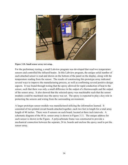
Figure 3.10. Small sensor array test setup.<br />
For the preliminary testing, a small Labview program was developed that read two temperature<br />
sensors and controlled the infrared heater. In this Labview program, the unique serial number of<br />
each attached sensor is read and shown on the bottom of the panel on the display, along with the<br />
temperature reading from the sensor. The results of constructing this prototype array indicated<br />
several ways to improve the manufacturing process, as well as confirming several positive design<br />
aspects. It was found through testing that the epoxy allowed <strong>for</strong> rapid conduction of heat to the<br />
sensor, such that there was only a small difference in the output of a thermocouple and the output<br />
of the sensor array. It also showed that the selected epoxy was machinable such that the sensor<br />
modules could be machined once the epoxy was set. The epoxy is expected to play a key role in<br />
protecting the sensors and wiring from the surrounding environment.<br />
A larger prototype sensor module was manufactured utilizing the in<strong>for</strong>mation learned. It<br />
consisted of two printed circuit boards attached together, each two feet in length <strong>for</strong> a total array<br />
length of 48 inches. There were 8 sensors on each board, located at three inch intervals. A<br />
schematic diagram of the 48 in. sensor array is shown in Figure 3.11. The unique address <strong>for</strong><br />
each sensor is shown in the Figure. A polycarbonate frame was constructed to provide a<br />
mechanical connection between the separate, 24 in. boards and enclose the epoxy used to pot the<br />
sensor array.<br />
14