Remote Health Monitoring for Asset Management
Remote Health Monitoring for Asset Management
Remote Health Monitoring for Asset Management

Create successful ePaper yourself
Turn your PDF publications into a flip-book with our unique Google optimized e-Paper software.
4 Laboratory Testing<br />
To evaluate the effectiveness of the sensor array developed, and to demonstrate the technology, a<br />
laboratory test set-up was developed. This test set-up included a HSS model pile, heating<br />
devices to impose a thermal gradient in the pile, and the data acquisition system to collect and<br />
store data from the sensors. This section of the report will provide details of the test set-up and<br />
results demonstrating the effectiveness of the sensor array. Measurements from the sensor array<br />
are included, as well as a comparison of the behavior of the sensor array and the thermal<br />
response of a thermocouple device. Per<strong>for</strong>mance of the sensor array in response to impressed<br />
thermal gradients is described. Results of a cold water test to demonstrate the anticipated<br />
thermal gradients in the pile are also included.<br />
Test Design<br />
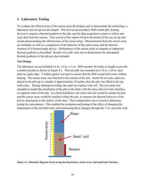
The laboratory set-up included a 6 in. x 6 in. x ½ in. HSS member 48 inches in length to provide<br />
a model test pile as shown in Figure 4.1. This test pile was mounted on a 18 in. x 24 in. steel<br />
plate by angle clips. A rubber gasket was used to ensure that the HSS would hold water without<br />
leaking. The sensor array was attached to the outside of the pile. Inside the test pile, sand was<br />
placed in the pile up to a height of approximetely 24 inches, then the pile was filled to the top<br />
with water. During subsequent testing, the sand was replace with soil. The test setup was<br />
intended to model the installation of the pile in the field, with the array and soil/water interface<br />
on opposite sides of the pile. In a field installation, the water and soil would be outside the pile<br />
and the sensor array would be installed within the pile, to measure the thermal behavior of the<br />
pile by attachment to the surface of the steel. This configuration was reversed in laboratory<br />
testing <strong>for</strong> convenience. This enabled the evaluaton and testing of the effect of changing the<br />
temperature of the soil and water, and measureing these changes through the ½ in. steel pile wall.<br />
Sensor array<br />
16 *<br />
15 *<br />
14 *<br />
13 *<br />
12 *<br />
11 *<br />
10 *<br />
9 *<br />
8 *<br />
7 *<br />
6 *<br />
5 *<br />
4 *<br />
3 *<br />
2 *<br />
1 *<br />
Water<br />
Sand / soil<br />
Heaters<br />
Figure 4.1. Schematic diagram of test set-up showing heaters, sensor array and sand/water interface.<br />
16