Remote Health Monitoring for Asset Management
Remote Health Monitoring for Asset Management
Remote Health Monitoring for Asset Management

Create successful ePaper yourself
Turn your PDF publications into a flip-book with our unique Google optimized e-Paper software.
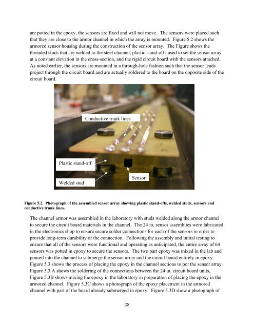
are potted in the epoxy, the sensors are fixed and will not move. The sensors were placed such<br />
that they are close to the armor channel in which the array is mounted. Figure 5.2 shows the<br />
armored sensor housing during the construction of the sensor array. The Figure shows the<br />
threaded studs that are welded to the steel channel, plastic stand-offs used to set the sensor array<br />
at a constant elevation in the cross-section, and the rigid circuit board with the sensors attached.<br />
As noted earlier, the sensors are mounted in a through-hole fashion such that the sensor leads<br />
project through the circuit board and are actually soldered to the board on the opposite side of the<br />
circuit board.<br />
Conductive trunk lines<br />
Plastic stand-off<br />
Welded stud<br />
Sensor<br />
Figure 5.2. Photograph of the assembled sensor array showing plastic stand-offs, welded studs, sensors and<br />
conductive trunk lines.<br />
The channel armor was assembled in the laboratory with studs welded along the armor channel<br />
to secure the circuit board materials in the channel. The 24 in. sensor assemblies were fabricated<br />
in the electronics shop to ensure secure solder connections <strong>for</strong> each of the sensors in order to<br />
provide long-term durability of the connection. Following the assembly and initial testing to<br />
ensure that all of the sensors were functional and operating as anticipated, the entire array of 64<br />
sensors was potted in epoxy to secure the sensors. The two part epoxy was mixed in the lab and<br />
poured into the channel to submerge the sensor array and the circuit board entirely in epoxy.<br />
Figure 5.3 shows the process of placing the epoxy in the channel sections to pot the sensor array.<br />
Figure 5.3 A shows the soldering of the connections between the 24 in. circuit board units,<br />
Figure 5.3B shows mixing the epoxy in the laboratory in preparation of placing the epoxy in the<br />
armored channel. Figure 5.3C shows a photograph of the epoxy placement in the armored<br />
channel with part of the board already submerged in epoxy. Figure 5.3D show a photograph of<br />
28