3to 11hp 4-cycle l-head engines - Small Engine Suppliers
3to 11hp 4-cycle l-head engines - Small Engine Suppliers
3to 11hp 4-cycle l-head engines - Small Engine Suppliers

Create successful ePaper yourself
Turn your PDF publications into a flip-book with our unique Google optimized e-Paper software.
OPERATION<br />
In the “CHOKE” or “START” position, the choke shutter is closed and the only air entering the engine enters through<br />
openings around the shutter. As the engine starts to rotate, downward piston travel creates a low air pressure area (or<br />
vacuum) above the piston. Higher pressure (atmospheric) air rushes into the engine and fills this low pressure area.<br />
Since the majority of the air passage is blocked by the choke shutter, a relatively small quantity of air enters the<br />
carburetor at an increased speed. The main nozzle and both idle fuel discharge ports are supplying fuel due to the low air<br />
pressure in the engine intake. Maximum fuel flow through the carburetor orifices combined with the reduced quantity of<br />
air that passes through the carburetor, make a very rich fuel mixture which is needed to start a cold engine.<br />
At engine IDLE speed, a relatively small amount of fuel is required to operate the engine. The throttle is almost completely<br />
closed. Fuel is supplied through the primary idle-fuel discharge orifice.<br />
NOTE: Dual system carburetors do not have an idle circuit.<br />
During INTERMEDIATE engine operation, a second orifice is uncovered as the throttle shutter opens, and more fuel<br />
is allowed to mix with the air flowing into the engine.<br />
During HIGH SPEED engine operation, the throttle shutter is fully opened. Air flows through the carburetor at high<br />
speed. The venturi, which decreases the size of the air passage through the carburetor, further accelerates the air<br />
flow. This high speed movement of the air decreases the air pressure at the main nozzle opening. Fuel is forced out<br />
the main nozzle opening due to the difference in the air pressure on the fuel in the carburetor bowl and the reduced<br />
air pressure at the main nozzle opening.<br />
For the fuel to flow, the carburetor bowl must be either<br />
vented externally or internally. Some internally vented float<br />
style carburetors use a tygon tube and a vent within the<br />
air intake. This tube must be present for the carburetor to<br />
operate properly (diag. 2).<br />
Air is bled into the main nozzle and through the air bleed<br />
located in the air horn. This mixes the fuel and air prior to<br />
the fuel leaving the main nozzle. Atomization occurs as<br />
the fuel mixture contacts the fast moving air stream. This<br />
mist then flows into the intake of the engine.<br />
FUEL PRIMERS<br />
TYGON TUBE<br />
LOCATION<br />
2<br />
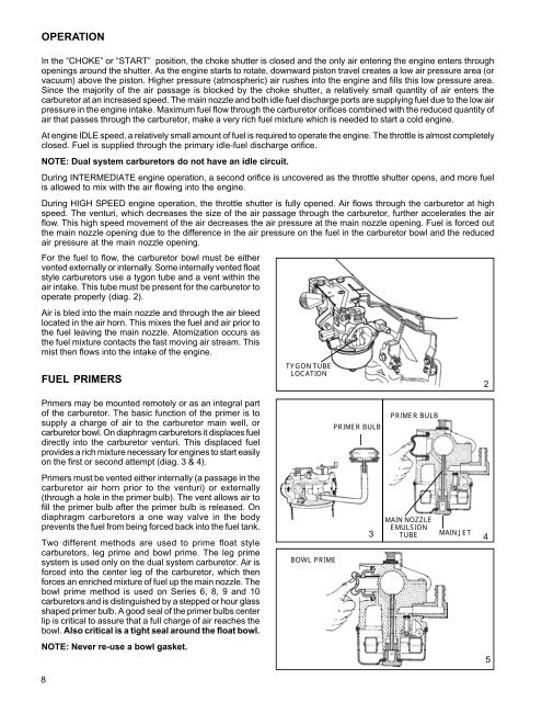
Primers may be mounted remotely or as an integral part<br />
of the carburetor. The basic function of the primer is to<br />
supply a charge of air to the carburetor main well, or<br />
carburetor bowl. On diaphragm carburetors it displaces fuel<br />
directly into the carburetor venturi. This displaced fuel<br />
provides a rich mixture necessary for <strong>engines</strong> to start easily<br />
on the first or second attempt (diag. 3 & 4).<br />
PRIMER BULB<br />
PRIMER BULB<br />
Primers must be vented either internally (a passage in the<br />
carburetor air horn prior to the venturi) or externally<br />
(through a hole in the primer bulb). The vent allows air to<br />
fill the primer bulb after the primer bulb is released. On<br />
diaphragm carburetors a one way valve in the body<br />
prevents the fuel from being forced back into the fuel tank.<br />
Two different methods are used to prime float style<br />
carburetors, leg prime and bowl prime. The leg prime<br />
system is used only on the dual system carburetor. Air is<br />
forced into the center leg of the carburetor, which then<br />
forces an enriched mixture of fuel up the main nozzle. The<br />
bowl prime method is used on Series 6, 8, 9 and 10<br />
carburetors and is distinguished by a stepped or hour glass<br />
shaped primer bulb. A good seal of the primer bulbs center<br />
lip is critical to assure that a full charge of air reaches the<br />
bowl. Also critical is a tight seal around the float bowl.<br />
BOWL PRIME<br />
3<br />
MAIN NOZZLE<br />
EMULSION<br />
TUBE<br />
MAIN JET<br />
4<br />
NOTE: Never re-use a bowl gasket.<br />
5<br />
8