3to 11hp 4-cycle l-head engines - Small Engine Suppliers
3to 11hp 4-cycle l-head engines - Small Engine Suppliers
3to 11hp 4-cycle l-head engines - Small Engine Suppliers

Create successful ePaper yourself
Turn your PDF publications into a flip-book with our unique Google optimized e-Paper software.
worn or damaged parts.<br />
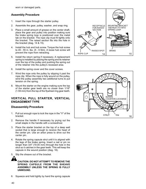
Assembly Procedure<br />
LEFT-HAND<br />
KNOT<br />
1. Insert the rope through the starter pulley.<br />
2. Assemble the gear, pulley, washer, and snap ring.<br />
3. Place a small amount of grease on the center shaft,<br />
place the gear and pulley into position making sure<br />
the brake spring loop is positioned over the metal<br />
tab on the bracket. The rope clip must fit tightly onto<br />
the bracket. The raised section fits into the hole in<br />
the bracket (diag. 14 & 15).<br />
RECEPTACLE<br />
FOR RAISED<br />
SECTION<br />
MOUNTING BRACKET<br />
TAB MUST FIT INTO<br />
SPRING LOOP<br />
4. Install the hub and hub screw. Torque the hub screw<br />
to 45 - 55 in. lbs. (5 - 6 Nm). A loose hub screw will<br />
prevent the rope from retracting.<br />
5. Install the return spring if necessary. A replacement<br />
spring is installed by placing the spring and its retainer<br />
over the top of the pulley and pushing the spring out<br />
of the retainer into the pulley's recessed area.<br />
ROPE CLIP<br />
RAISED SPOT<br />
14<br />
BRAKE<br />
15<br />
6. Install the spring cover and the cover screws.<br />
7. Wind the rope onto the pulley by slipping it past the<br />
rope clip. When the rope is fully wound on the pulley,<br />
wind the pulley assembly two additional turns to put<br />
tension on the spring.<br />
8. Mount the starter on the engine making sure the top<br />
of the starter gear teeth are no closer than 1/16"<br />
(1.59 mm) from the top of the flywheel ring gear teeth.<br />
VERTICAL PULL STARTER, VERTICAL<br />
ENGAGEMENT TYPE<br />
ROTATE<br />
COUNTERCLOCKWISE<br />
Disassembly Procedure<br />
1. Pull out enough rope to lock the rope in the "V" of the<br />
bracket.<br />
STRUT<br />
PIN<br />
16<br />
2. Remove the handle if necessary by prying out the<br />
small staple in the handle with a screwdriver.<br />
3. Place the starter bracket on the top of a deep well<br />
socket that is large enough to receive the <strong>head</strong> of<br />
the center pin. Use an arbor press to drive out the<br />
center pin.<br />
4. Rotate the spring capsule strut until it is aligned with<br />
the legs of the brake spring. Insert a nail or pin no<br />
longer than 3/4" (19.05 mm) through the hole in the<br />
strut so it catches in the gear teeth. This will keep the<br />
capsule in the wound position (diag. 16).<br />
5. Slip the sheave out of the bracket.<br />
CAUTION: DO NOT ATTEMPT TO REMOVE THE<br />
SPRING CAPSULE FROM THE SHEAVE<br />
ASSEMBLY UNLESS THE SPRING IS FULLY<br />
UNWOUND.<br />
6. Squeeze and hold tightly by hand the spring capsule<br />
40