3to 11hp 4-cycle l-head engines - Small Engine Suppliers
3to 11hp 4-cycle l-head engines - Small Engine Suppliers
3to 11hp 4-cycle l-head engines - Small Engine Suppliers

Create successful ePaper yourself
Turn your PDF publications into a flip-book with our unique Google optimized e-Paper software.
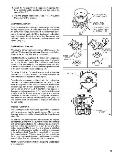
4. Install the hinge pin from the opposite hinge leg. The<br />
bowl gasket must be positioned over the end of the<br />
spring (diag. 51).<br />
5. Set the proper float height. See “Float Adjusting<br />
Procedure” in this chapter.<br />
GASKET GOES<br />
OVER SPRING<br />
Diaphragm Assembly<br />
CHOKE END OF<br />
CARBURETOR<br />
The rivet <strong>head</strong> on the diaphragm must always face toward<br />
the inlet needle valve. On carburetors with an “F” cast into<br />
the carburetor flange as illustrated, the diaphragm goes<br />
next to the carburetor body. Other diaphragm carburetors<br />
have the gasket located between the diaphragm and<br />
carburetor body. Install the cover retaining screws and<br />
tighten (diag. 52).<br />
ENDS OF SPRING POINT<br />
TOWARD CHOKE END<br />
OF CARBURETOR<br />
51<br />
Fuel Bowl And Bowl Nut<br />
Whenever a carburetor bowl is removed for service, the<br />
fuel bowl “O” ring must be replaced. For easier installation,<br />
lubricate the “O” ring with a small amount oil.<br />
Install the float bowl by placing the detent portion opposite<br />
of the hinge pin. Make sure the deepest end of the bowl is<br />
opposite of the inlet needle. The bowl has a small dimple<br />
located in the deepest part. The purpose of this dimple is<br />
to minimize the chances of the float sticking to the bottom<br />
of the bowl caused by stale fuel (diag. 53).<br />
RIDGE AND<br />
RIVET<br />
HEAD UP<br />
GASKET<br />
RIDGE AND<br />
RIVET HEAD<br />
UP<br />
GASKET<br />
52<br />
On some fixed jet (non-adjustable) and adjustable<br />
carburetors, a fibered washer is required between the<br />
carburetor bowl and the bowl retaining nut.<br />
DETENT<br />
Occasionally, on <strong>engines</strong> equipped with the dual system<br />
carburetor, some rich starting conditions have occurred<br />
when the engine is warm. This condition can be corrected<br />
by inserting a non-metallic spacer in the center leg of the<br />
carburetor, as shown (part # 632158). This spacer is<br />
designed to reduce the amount of prime charge in the main<br />
nozzle area for better starting under warm engine<br />
conditions. It can only be used on Dual System carburetors<br />
and does not lean out the carburetor mixture. (diag. 54)<br />
This spacer must be reinstalled if originally equipped in<br />
the carburetor.<br />
53<br />
Impulse Fuel Pump<br />
The diaphragms must be installed against the center body<br />
with the gaskets against the outside covers. The parts are<br />
designed so they cannot be misassembled without damage<br />
(diag. 54).<br />
NON-METALLIC<br />
SPACER<br />
54<br />
To test the unit, assemble the carburetor to the engine,<br />
leaving the fuel line from the pump off. Use a different fuel<br />
tank remotely placed above the carburetor to provide gravity<br />
fuel flow to the carburetor inlet to run the engine while<br />
testing the pump. Make sure fuel is available in both fuel<br />
tanks and that the original fuel tank's fuel line is connected<br />
to the fuel pump inlet. Place the pump outlet line in a proper<br />
draining receptacle. With the pulse line connected from<br />
the engine crankcase to the pump and the engine running,<br />
a definite fuel flow should result at the pump outlet.<br />
If the flow is erratic or intermittent, the pump needs repair<br />
or replacement.<br />
23