3to 11hp 4-cycle l-head engines - Small Engine Suppliers
3to 11hp 4-cycle l-head engines - Small Engine Suppliers
3to 11hp 4-cycle l-head engines - Small Engine Suppliers

You also want an ePaper? Increase the reach of your titles
YUMPU automatically turns print PDFs into web optimized ePapers that Google loves.
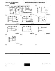
7 Amp Alternator System Regulator-<br />
Rectifier Under <strong>Engine</strong> Block Housing<br />
Models: H50-60, HH50-60, HM70-80-100,<br />
HHM80, TVM125-140-170-195-220<br />
In this system, the regulator and rectifier are combined<br />
in one solid state unit mounted under the blower housing<br />
of the engine.<br />
MAGNETO GROUND - GREEN<br />
Various types of regulator-rectifiers have been used on<br />
different applications. Test procedures for all types are<br />
the same. However, regulator styles are not<br />
interchangeable (diag. 28).<br />
CHECKING THE SYSTEM: An open circuit D.C. voltage<br />
check cannot be made with this system. If a known good<br />
battery fails to maintain a charge, proceed to make an<br />
A.C. voltage test.<br />
D.C. OUTPUT LEAD-RED<br />
28<br />
To do this, the blower housing must be removed, and the<br />
regulator-rectifier must be brought outside of the blower<br />
housing.<br />
Keep the A.C. leads attached to the regulator-rectifier.<br />
Install the blower housing with the regulator-rectifier<br />
outside the housing. With an A.C. voltmeter probe the<br />
regulator as shown (diag. 29)<br />
CAUTION: AT NO TIME SHOULD THE ENGINE<br />
BE STARTED WITH THE BLOWER HOUSING<br />
REMOVED.<br />
With engine running, minimum A.C. voltage from lead to<br />
lead should be:<br />
2500 R.P.M. - 16.0 Volts A.C.<br />
3000 R.P.M. - 19.0 Volts A.C.<br />
3300 R.P.M. - 21.0 Volts A.C.<br />
3600 R.P.M. - 23.0 Volts A.C.<br />
If the minimum readings are noted, the alternator is okay.<br />
If the system fails to charge a known good battery, the<br />
regulator-rectifier must be defective.<br />
10 Amp Alternator System - Regulator-<br />
Rectifier-External to <strong>Engine</strong><br />
CAUTION: BLOWER<br />
HOUSING MUST BE<br />
INSTALLED WHEN<br />
RUNNING ENGINE<br />
B+ TERMINAL WIRE<br />
INSERT PROBES INTO<br />
CONNECTOR SLOTS<br />
DO NOT REMOVE<br />
CONNECTOR WIRES<br />
YELLOW<br />
RED<br />
A.C. VOLTMETER<br />
29<br />
In this system, the regulator and rectifier are combined<br />
in one solid state unit.<br />
CHECKING THE SYSTEM: To check the system,<br />
disconnect the D.C. or B+ wire at the switch end and<br />
measure D.C. voltage between the lead and ground (diag.<br />
30).<br />
GREEN<br />
YELLOW<br />
REGULATOR/<br />
RECTIFIER MUST BE<br />
GROUNDED<br />
30<br />
With the engine running, minimum values should read:<br />
2500 R.P.M. - 13.0 Volts D.C.<br />
3000 R.P.M. - 16.0 Volts D.C.<br />
3600 R.P.M. - 20.0 Volts D.C.<br />
If the minimum values are noted, the system is okay.<br />
Check for defective ammeter, wiring, etc. If less than the<br />
above readings, disconnect the plug from the regulatorrectifier,<br />
and insert the A.C. voltmeter probes in the two<br />
outside terminals (diag. 31).<br />
(continued on top of next page)<br />
31<br />
55