3to 11hp 4-cycle l-head engines - Small Engine Suppliers
3to 11hp 4-cycle l-head engines - Small Engine Suppliers
3to 11hp 4-cycle l-head engines - Small Engine Suppliers

Create successful ePaper yourself
Turn your PDF publications into a flip-book with our unique Google optimized e-Paper software.
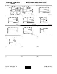
SERVICE<br />
This section covers the service procedures for the 12 and 120 volt electric starters. For diagnosis of the starting circuit<br />
see “Electrical Starter Troubleshooting” in this chapter. Illustrations may not be identical in configuration to the starter<br />
being serviced, but procedures and tests apply unless otherwise stated.<br />
12 VOLT OR 120 VOLT ELECTRIC STARTERS<br />
WITH EXPOSED SHAFT<br />
1. Remove the plastic dust cover on the armature end<br />
(diag. 34).<br />
2. Push down the spring retainer and remove the<br />
retainer ring.<br />
3. Slide off the spring retainer, anti-drift spring, gear,<br />
and drive nut.<br />
4. If internal service is necessary, scribe a line across<br />
the cap assemblies and armature housing to aid in<br />
reassembly.<br />
5. Remove the two or four retaining nuts from the<br />
through bolts holding the cap assembly.<br />
6. Slide off the cap assembly. The terminal insulator<br />
slides out of the commutator cap.<br />
7. Remove the armature.<br />
34<br />
8. Inspect and replace as necessary.<br />
9. Use the reverse procedure for reassembly.<br />
10. Inspect flywheel ring gear for damage before<br />
installation.<br />
GEAR<br />
SPRING<br />
RETAINER<br />
RING<br />
ARMATURE<br />
12 VOLT D.C. OR 120 VOLT A.C. ELECTRIC<br />
STARTERS WITH CAP ASSEMBLY<br />
1. Remove the retainer ring from the armature shaft<br />
(diag.35).<br />
2. Remove the two nuts from the through bolts holding<br />
the cap assembly on.<br />
DRIVE NUT<br />
SPRING<br />
RETAINER<br />
CAP ASSY.<br />
35<br />
3. Slide off the cap assembly. The engaging nut, gear,<br />
spring, and spring retainer will remain in the cap<br />
assembly.<br />
4. If complete disassembly is required, refer to step # 4<br />
in the previous section for additional steps.<br />
5. Inspect and replace as necessary. Use reverse<br />
procedure for assembly. ( For ease of assembly, place<br />
the armature into the brush end frame first.)<br />
6. Inspect flywheel ring gear for damage before<br />
installation.<br />
(continued on top of next page)<br />
57