3to 11hp 4-cycle l-head engines - Small Engine Suppliers
3to 11hp 4-cycle l-head engines - Small Engine Suppliers
3to 11hp 4-cycle l-head engines - Small Engine Suppliers

Create successful ePaper yourself
Turn your PDF publications into a flip-book with our unique Google optimized e-Paper software.
GENERAL INFORMATION<br />
CHAPTER 6 ELECTRICAL SYSTEMS<br />
The electrical system consists of three main elements: a battery, a starting circuit, and a charging circuit. The battery<br />
is part of both the starting and charging circuit. The battery should be checked before going into any extensive starter<br />
or charging system checks. If a battery has a shorted cell, overcharging can result, and the regulator or rectifier may<br />
appear to be at fault. If a cell has an open or high resistance connection, the electric starter operation will be affected.<br />
The power source used to provide the energy to turn an electric starter motor on Tecumseh <strong>engines</strong> is either 120 volt<br />
A.C. current or 12 volt D.C. An A.C. starter circuit utilizes a 120 volt power source instead of a battery. The 12 volt<br />
battery models require a charging system to maintain proper battery charge.<br />
The starting circuit includes the battery, battery cables, starter or ignition switch, safety switches, and an electric<br />
starter motor.<br />
The charging system consists of alternator charge coils, rectifiers or diodes, regulator, ignition switch, flywheel magnets,<br />
and a battery. All <strong>engines</strong> that have a charging system will use a combination of some or all of these features.<br />
OPERATION<br />
STARTING CIRCUIT AND ELECTRIC<br />
STARTERS<br />
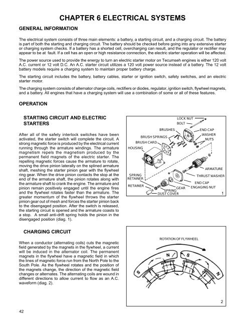
After all of the safety interlock switches have been<br />
activated, the starter switch will complete the circuit. A<br />
strong magnetic force is produced by the electrical current<br />
running through the armature windings. The armature<br />
magnetism repels the magnetism produced by the<br />
permanent field magnets of the electric starter. The<br />
repelling magnetic forces cause the armature to rotate,<br />
moving the drive pinion laterally on the splined armature<br />
shaft, meshing the starter pinion gear with the flywheel<br />
ring gear. When the drive pinion contacts the stop at the<br />
end of the armature shaft, the pinion rotates along with<br />
the armature shaft to crank the engine. The armature and<br />
pinion remain positively engaged until the engine fires<br />
and the flywheel rotates faster than the armature. The<br />
greater momentum of the flywheel throws the starter<br />
pinion gear out of mesh and forces the starter pinion back<br />
to the disengaged position. After the switch is released,<br />
the starting circuit is opened and the armature coasts to<br />
a stop. A small anti-drift spring holds the pinion in the<br />
disengaged position (diag. 1).<br />
HOUSING<br />
SPRING<br />
RETAINER<br />
BRUSH CARD<br />
RETAINER<br />
BRUSHES<br />
BRUSH SPRINGS<br />
LOCK NUT<br />
BOLT<br />
SPRING GEAR<br />
DUST COVER<br />
END CAP<br />
WASHER<br />
NUTS<br />
ARMATURE<br />
THRUST WASHER<br />
END CAP<br />
ENGAGING NUT<br />
1<br />
CHARGING CIRCUIT<br />
When a conductor (alternating coils) cuts the magnetic<br />
field generated by the magnets in the flywheel, a current<br />
will be induced in the alternator coil. The permanent<br />
magnets in the flywheel have a magnetic field in which<br />
the lines of magnetic force run from the North Pole to the<br />
South Pole. As the flywheel rotates and the position of<br />
the magnets change, the direction of the magnetic field<br />
changes or alternates. The alternating coils are wound in<br />
different directions to allow current to flow as an A.C.<br />
waveform (diag. 2).<br />
ROTATION OF FLYWHEEL<br />
2<br />
42