2010 Kenworth T440/T470 Body Builder Manual
2010 Kenworth T440/T470 Body Builder Manual
2010 Kenworth T440/T470 Body Builder Manual
- No tags were found...

Create successful ePaper yourself
Turn your PDF publications into a flip-book with our unique Google optimized e-Paper software.
Section 7<br />
Frame Modifications<br />
MODIFYING FRAME LENGTH<br />
The frame cutoff after the rear axle can be shortened to match a particular body length. Using a torch is acceptable;<br />
however, heat from a torch will affect the material characteristics of the frame rail. The affected material will normally be<br />
confi ned to within 1 to 2 inches (25 to 50 mm) of the fl ame cut and may not adversely affect the strength of the chassis or<br />
body installation.<br />
The frame cutoff can be lengthened by adding frame extenders.<br />
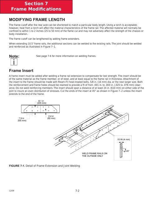
When extending 10.5” frame rails, the additional sections can be welded to the existing rails. The joint should be welded<br />
and reinforced as illustrated in Figure 7–1.<br />
Note:<br />
See page 7-6 for more information on welding frames.<br />
Frame Insert<br />
A frame insert must be added after welding a frame rail extension to compensate for lost strength. The insert should be<br />
of the same material as the frame member, or of steel, and at least equal to the frame rail in thickness. Attachment of<br />
the insert to the frame should be made with Ream-Fit heat-treated bolts, 5/8 in. (16 mm) dia. or the next larger size. Both<br />
the reinforcement and frame holes should be reamed to provide a fit of from .001 in. to .003 in. (.025 to .076 mm) clearance.<br />
Do not weld reinforcing members. The insert should span a distance of at least 24 in. (610 mm) on either side of the<br />
joint to insure an even distribution of stresses. Cut the ends of the insert at 45° as shown in Figure 7–2 unless the insert<br />
extends to the end of the frame.<br />
FIGURE 7-1. Detail of Frame Extension and Joint Welding<br />
12/09<br />
7-2