2010 Kenworth T440/T470 Body Builder Manual
2010 Kenworth T440/T470 Body Builder Manual
2010 Kenworth T440/T470 Body Builder Manual
- No tags were found...

Create successful ePaper yourself
Turn your PDF publications into a flip-book with our unique Google optimized e-Paper software.
Section 4<br />
Exhaust & Aftertreatment<br />
Vertical DPF and SCR with Clear Back of Cab DEF Tank<br />
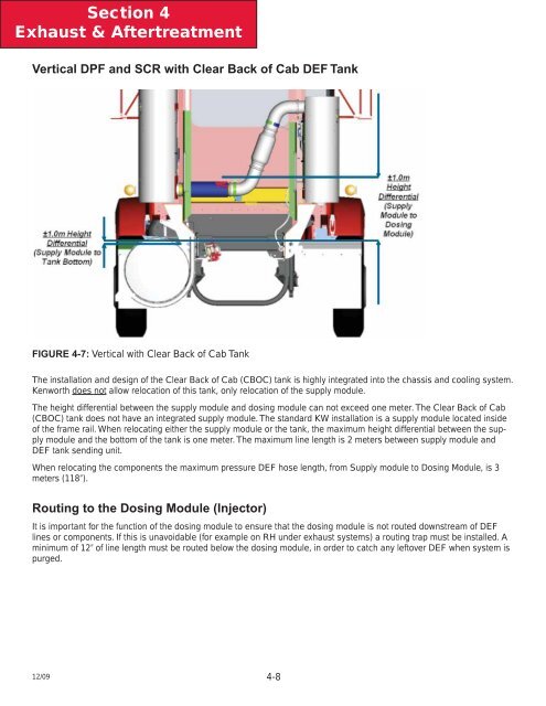
FIGURE 4-7: Vertical with Clear Back of Cab Tank<br />
The installation and design of the Clear Back of Cab (CBOC) tank is highly integrated into the chassis and cooling system.<br />
<strong>Kenworth</strong> does not allow relocation of this tank, only relocation of the supply module.<br />
The height differential between the supply module and dosing module can not exceed one meter. The Clear Back of Cab<br />
(CBOC) tank does not have an integrated supply module. The standard KW installation is a supply module located inside<br />
of the frame rail. When relocating either the supply module or the tank, the maximum height differential between the supply<br />
module and the bottom of the tank is one meter. The maximum line length is 2 meters between supply module and<br />
DEF tank sending unit.<br />
When relocating the components the maximum pressure DEF hose length, from Supply module to Dosing Module, is 3<br />
meters (118”).<br />
Routing to the Dosing Module (Injector)<br />
It is important for the function of the dosing module to ensure that the dosing module is not routed downstream of DEF<br />
lines or components. If this is unavoidable (for example on RH under exhaust systems) a routing trap must be installed. A<br />
minimum of 12” of line length must be routed below the dosing module, in order to catch any leftover DEF when system is<br />
purged.<br />
12/09 4-8