2010 Kenworth T440/T470 Body Builder Manual
2010 Kenworth T440/T470 Body Builder Manual
2010 Kenworth T440/T470 Body Builder Manual
- No tags were found...

Create successful ePaper yourself
Turn your PDF publications into a flip-book with our unique Google optimized e-Paper software.
Section 7<br />
Frame Modifications<br />
WELDED<br />
JOINT<br />
24 Inch<br />
Minimum<br />
(610 mm)<br />
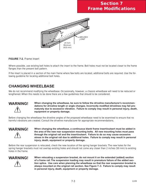
FIGURE 7-2. Frame Insert<br />
Where possible, use existing bolt holes to attach the insert to the frame. Bolt holes must not be located closer to the frame<br />
fl anges than the present bolt pattern.<br />
If the insert is placed in a section of the main frame where few bolts are located, additional bolts are required. Use the following<br />
guideline for locating additional bolt holes.<br />
CHANGING WHEELBASE<br />
We do not recommend modifying the wheelbase. Occasionally, however, a chassis wheelbase will need to be reduced or<br />
lengthened. When this needs to be done there are a few guidelines that should to be considered.<br />
WARNING!<br />
When changing the wheelbase, be sure to follow the driveline manufacturer’s recommendations<br />
for driveline length or angle changes. Incorrectly modified drivelines may fail prematurely<br />
due to excessive vibration. Failure to comply may result in personal injury, death,<br />
equipment or property damage.<br />
Before changing the wheelbase the driveline angles of the proposed wheelbase need to be examined to ensure that no<br />
harmful vibrations are created. Consult the driveline manufacturer for appropriate recommendations.<br />
WARNING!<br />
When changing the wheelbase, a continuous blank frame insert/outsert must be added in<br />
the area of the new rear suspension mounting bolts. All new mounting holes must pass<br />
through the original rail and the insert/outsert. Failure to do so may cause excessive<br />
stress in the original rail due to additional holes. Failure to comply may result in personal<br />
injury, death, equipment or property damage.<br />
Before the rear suspension is relocated, check the new location of the spring hanger brackets. The new holes for the<br />
spring hanger brackets must not overlap existing holes and should not come any closer than 2 inches (50 mm) to existing<br />
holes in the frame.<br />
WARNING!<br />
When relocating a suspension bracket, do not mount it on the extended (added) section<br />
of a frame rail. The suspension loading may result in premature failure of the added section<br />
splice. Use care when planning the wheelbase so that the rear suspension bracket is<br />
always mounted on the original rail section. See Figure 7–3. Failure to comply may result<br />
in personal injury, death, equipment or property damage.<br />
7-3<br />
12/09