2010 Kenworth T440/T470 Body Builder Manual
2010 Kenworth T440/T470 Body Builder Manual
2010 Kenworth T440/T470 Body Builder Manual
- No tags were found...

Create successful ePaper yourself
Turn your PDF publications into a flip-book with our unique Google optimized e-Paper software.
Section 4<br />
Exhaust & Aftertreatment<br />
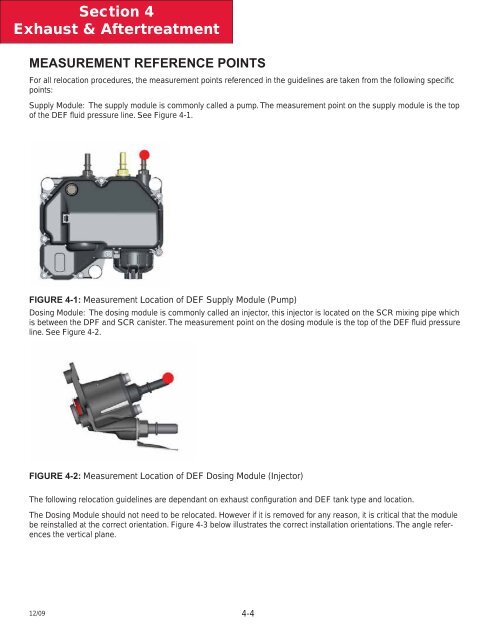
MEASUREMENT REFERENCE POINTS<br />
For all relocation procedures, the measurement points referenced in the guidelines are taken from the following specific<br />
points:<br />
Supply Module: The supply module is commonly called a pump. The measurement point on the supply module is the top<br />
of the DEF fl uid pressure line. See Figure 4-1.<br />
FIGURE 4-1: Measurement Location of DEF Supply Module (Pump)<br />
Dosing Module: The dosing module is commonly called an injector, this injector is located on the SCR mixing pipe which<br />
is between the DPF and SCR canister. The measurement point on the dosing module is the top of the DEF fluid pressure<br />
line. See Figure 4-2.<br />
FIGURE 4-2: Measurement Location of DEF Dosing Module (Injector)<br />
The following relocation guidelines are dependant on exhaust configuration and DEF tank type and location.<br />
The Dosing Module should not need to be relocated. However if it is removed for any reason, it is critical that the module<br />
be reinstalled at the correct orientation. Figure 4-3 below illustrates the correct installation orientations. The angle references<br />
the vertical plane.<br />
12/09 4-4