

Wire Harness Installation Instructions For Installing - Painless Wiring
Wire Harness Installation Instructions For Installing - Painless Wiring
Wire Harness Installation Instructions For Installing - Painless Wiring

You also want an ePaper? Increase the reach of your titles
YUMPU automatically turns print PDFs into web optimized ePapers that Google loves.
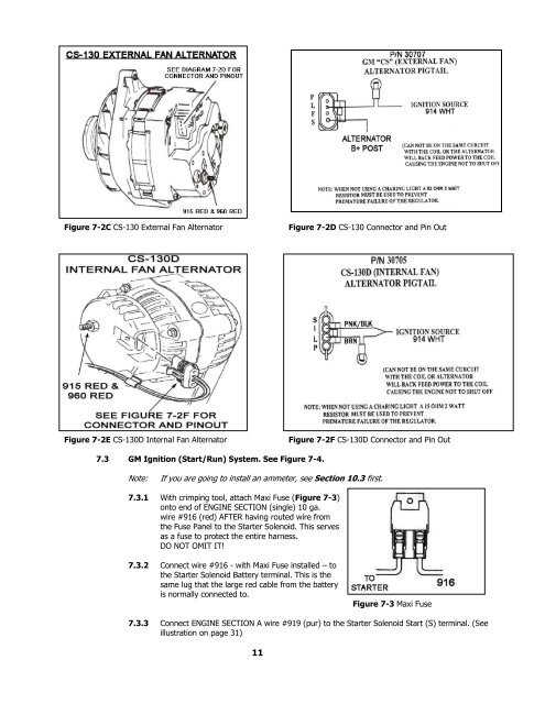
Figure 7-2C CS-130 External Fan Alternator<br />
Figure 7-2D CS-130 Connector and Pin Out<br />
Figure 7-2E CS-130D Internal Fan Alternator<br />
Figure 7-2F CS-130D Connector and Pin Out<br />
7.3 GM Ignition (Start/Run) System. See Figure 7-4.<br />
Note:<br />
If you are going to install an ammeter, see Section 10.3 first.<br />
7.3.1 With crimping tool, attach Maxi Fuse (Figure 7-3)<br />
onto end of ENGINE SECTION (single) 10 ga.<br />
wire #916 (red) AFTER having routed wire from<br />
the Fuse Panel to the Starter Solenoid. This serves<br />
as a fuse to protect the entire harness.<br />
DO NOT OMIT IT!<br />
7.3.2 Connect wire #916 - with Maxi Fuse installed – to<br />
the Starter Solenoid Battery terminal. This is the<br />
same lug that the large red cable from the battery<br />
is normally connected to.<br />
Figure 7-3 Maxi Fuse<br />
7.3.3 Connect ENGINE SECTION A wire #919 (pur) to the Starter Solenoid Start (S) terminal. (See<br />
illustration on page 31)<br />
11


