Wire Harness Installation Instructions For Installing - Painless Wiring
Wire Harness Installation Instructions For Installing - Painless Wiring
Wire Harness Installation Instructions For Installing - Painless Wiring
Create successful ePaper yourself
Turn your PDF publications into a flip-book with our unique Google optimized e-Paper software.
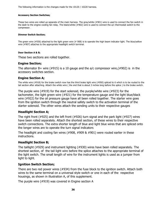
The following information is the changes made for the 10120 / 10220 harness.<br />
Accessory Section Switches;<br />
These two wires are rolled up separate of the main harness. The gray/white (#901) wire is used to connect the fan switch in<br />
the dash to the engine cooling fan relay. The black/white (#902) wire is used to connect the a/c thermostat switch to the<br />
compressor.<br />
Dimmer Switch Section;<br />
The green wire (#936) attached to the light green wire (# 908) is to operate the high beam indicator light. The blue/yellow<br />
wire (#907) attaches to the appropriate headlight switch terminal.<br />
Door Section A & B;<br />
These two sections are rolled together.<br />
Engine Section;<br />
The alternator B+ wire (#915) is a 10 gauge and the a/c compressor wire,(#902) is in the<br />
accessory switches section.<br />
Engine Section A;<br />
The white wire (#918) for the brake switch now has the third brake light wire (#950) spliced to it which is to be routed to the<br />
tail section after attaching. Attach the white wire ( the end that is about 3 inches long before the splice ) to the brake switch.<br />
The purple wire (#919) for the start solenoid, the purple/white wire (#923) for the<br />
tachometer, the light green wire (#921) for the temperature gauge and the light blue/black<br />
wire (#922) for the oil pressure gauge have all been rolled together. The starter wire goes<br />
from the ignition switch through the neutral safety switch to the activation terminal of the<br />
starter solenoid. The other wires attach the sending units to their respective gauges<br />
Headlight Section A;<br />
The right front (#925) and the left front (#926) turn signal and the park light (#927) wires<br />
have been rolled separately. Attach the shortest section, of these wires to their respective<br />
switch connections. The extra shorter length of blue and light blue wires that are spliced onto<br />
the longer wires are to operate the turn signal indicators<br />
The headlight and cooling fan wires (#908, #909 & #901) were routed earlier in these<br />
instructions.<br />
Headlight Section B;<br />
The taillight (#929) and instrument lighting (#930) wires have been rolled separately. The<br />
shortest section, of the tail light wire before the splice attaches to the appropriate terminal of<br />
the light switch. The small length of wire for the instrument lights is used as a jumper from<br />
light to light.<br />
Ignition Switch Section;<br />
There are two red power wires (#934) from the fuse block to the ignition switch. Attach both<br />
wires to the same terminal on a universal style switch or one in each of the respective<br />
housings, as shown in illustration A, of this supplement.<br />
The purple wire (#919) was covered in Engine section A<br />
36


