

Wire Harness Installation Instructions For Installing - Painless Wiring
Wire Harness Installation Instructions For Installing - Painless Wiring
Wire Harness Installation Instructions For Installing - Painless Wiring

Create successful ePaper yourself
Turn your PDF publications into a flip-book with our unique Google optimized e-Paper software.
7.3.4 If you are using the Ballast Resistor, mount it away<br />
from other wiring or hoses. The Ballast Resistor gets<br />
very hot during operation. Connect ENGINE<br />
SECTION A wire #920 (pnk) to one end of the Ballast<br />
Resistor. Connect the other end of the Ballast Resistor<br />
to the Ignition Coil B+ terminal with 14-gauge wire<br />
(you may have enough pink wire left over to<br />
accomplish this). If you are not using a Ballast<br />
Resistor, connect wire #920 directly to the Ignition<br />
Coil B+ terminal.<br />
Note: The ballast resistor has been deleted from<br />
this kit due to lack of consumer usage. If one is<br />
needed in your application, please call <strong>Painless</strong><br />
Performance at 800-423-9696 for assistance.<br />
Important Note! <strong>For</strong> HEI systems route wire<br />
#920 (pnk) to the Distributor and attach it to<br />
the terminal labeled BAT. No Ballast Resistor<br />
is required.<br />
Figure 7-4 GM Ignition (Start-Run) System<br />
7.3.5 The Ignition Coil NEGATIVE (-) terminal is connected to the Distributor. Also Connect ENGINE SECTION A<br />
wire #923 (pur/wht) to the Ignition Coil NEGATIVE (-) terminal. This is the tachometer source. If you are<br />
not using a tachometer, insulate and stow wire #923.<br />
7.3.6 A 14-gauge wire connected from the Starter Solenoid Ignition (l) terminal to the ignition coil side of the<br />
Ballast Resistor is optional. This wire (the dashed line in Figure 7-4) serves as a ballast resistor BYPASS<br />
during engine starting. However, if the starter solenoid shorts out, which is not unusual, the engine will stop<br />
running and will not restart as long as this wire is connected. You may therefore choose to omit it. If you<br />
are not using a Ballast Resistor, leave the Starter Solenoid Ignition (l) terminal unconnected and do not<br />
install the bypass wire.<br />
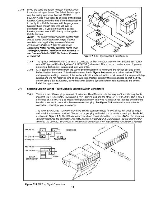
7.4 Steering Column <strong>Wiring</strong> - Turn Signal & Ignition Switch Connectors<br />
7.4.1 There are two different plugs on most tilt columns. The difference is in the length of the male plug that is<br />
mounted ON THE COLUMN. One plug is 3-7/8” (3.875”) long and the other is 4-1/4" (4.250"). This is only a<br />
difference of 3/8" (0.375"), so measure the plug carefully. The <strong>Wire</strong> <strong>Harness</strong> Kit has included two different<br />
female connectors to mate with the column-mounted plug. See Figure 7-5 to determine which female<br />
connector is correct for your automobile.<br />
The TURN SIGNAL SECTION wires may have already been terminated for you. If not, cut wires to length<br />
and install the terminals provided. Choose the proper plug and install the terminals according to Table 7-1,<br />
as shown in Figure 7-5. The GM wire color codes have been included for reference. Note: The terminals<br />
will only insert into the connector ONE WAY, as shown in Figure 7-5. Make certain you are inserting the<br />
wire into the CORRECT LOCATION as the terminals are difficult if not impossible to remove once inserted.<br />
Figure 7-5 GM Turn Signal Connectors<br />
12


