

Wire Harness Installation Instructions For Installing - Painless Wiring
Wire Harness Installation Instructions For Installing - Painless Wiring
Wire Harness Installation Instructions For Installing - Painless Wiring

Create successful ePaper yourself
Turn your PDF publications into a flip-book with our unique Google optimized e-Paper software.
Figure 10-5 Dimmer Switches (Push Button Style – <strong>Painless</strong> Part #80150)<br />
10.6 HEADLIGHT SECTION B <strong>Wiring</strong>. See Figure 10-6.<br />
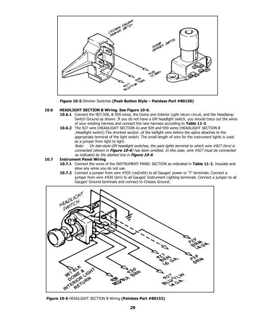
10.6.1 Connect the 907,928, & 959 wires, the Dome and Interior Light return circuit, and the Headlamp<br />
Switch Ground as shown. If you do not have a GM headlight switch, you should trace out the wires<br />
of your existing harness and connect the new harness according to Table 11-2.<br />
10.6.2 The 927 wire (HEADLIGHT SECTION A) and 929 and 930 wires (HEADLIGHT SECTION B<br />
,Headlight switch).The shortest section ,of the taillight wire before the splice attaches to the<br />
appropriate terminal of the light switch. The small length of wire for the instrument lights is used<br />
as a jumper from light to light.<br />
Note: On late-style GM headlight switches, the park lights terminal to which wire #927 (brn) is<br />
connected (shown in Figure 10-6) has been omitted. In this case, wire #927 must be connected<br />
as indicated by the dashed line in Figure 10-6.<br />
10.7 Instrument Panel <strong>Wiring</strong><br />
10.7.1 Connect the wires of the INSTRUMENT PANEL SECTION as indicated in Table 11-2. Insulate and<br />
stow any wires you do not use.<br />
10.7.2 Connect a jumper from wire #935 (red/wht) to all Gauges' power or “I” terminals. Connect a<br />
jumper from wire #930 (brn) to all Gauges' Instrument Lighting terminals. Connect a jumper to all<br />
Gauges' Ground terminals and connect to Chassis Ground.<br />
Figure 10-6 HEADLIGHT SECTION B <strong>Wiring</strong> (<strong>Painless</strong> Part #80152)<br />
29


