

Wire Harness Installation Instructions For Installing - Painless Wiring
Wire Harness Installation Instructions For Installing - Painless Wiring
Wire Harness Installation Instructions For Installing - Painless Wiring

You also want an ePaper? Increase the reach of your titles
YUMPU automatically turns print PDFs into web optimized ePapers that Google loves.
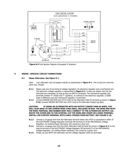
Figure 8-5 <strong>For</strong>d Ignition Diagram (Duraspark II Systems)<br />
9 MOPAR - SPECIFIC CIRCUIT CONNECTIONS<br />
9.1 Mopar Alternator. See Figure 9-1<br />
Note: Your Alternator may not appear exactly as represented in Figure 9-1. The circuits are wired the<br />
same way, though.<br />
9.1.1 Mopar uses one of two kinds of voltage regulators: An electronic regulator and a mechanical one.<br />
The electronic voltage regulator is represented in Figure 9-1. It does not matter how the two<br />
terminals are connected, so long as they are BOTH connected. The mechanical regulator has<br />
terminals marked "F" (Field) and "l" (Ignition). In contrast to the electronic regulator, it DOES<br />
make a difference how the mechanical regulator is connected.<br />
9.1.2 Connect ENGINE SECTION wire #914 (wht) to the Alternator Field (F) terminal as shown in Figure<br />
9-1A. Connect ENGINE SECTION wire #915 (red) to the Alternator Output lug (Bat).<br />
CAUTION: IF USING AN ALTERNATOR WITH AN OUTPUT LARGER THAN 65 AMPS, YOU<br />
WILL ALSO NEED TO USE JUMPER WIRE #960 (RED), INCLUDED IN BOX. THE WIRE END WITH<br />
THE RING TERMINAL AND RUBBER BOOT WILL CONNECT TO THE ALTERNATOR OUTPUT LUG.<br />
ROUTE THE OTHER END TO THE STARTER. CUT THE WIRE AND CRIMP ON A RING TERMINAL.<br />
INSTALL ON STARTER TERMINAL WITH CABLE COMING FROM BATTERY. SEE FIGURE 9-1B.<br />
9.1.3 Connect a 14-gauge wire from the Alternator terminal where wire #914 is connected to either of<br />
the ELECTRONIC Voltage Regulator terminals OR terminal (l) of the MECHANICAL Voltage<br />
Regulator. On existing Mopar harnesses, this would be a blue wire.<br />
9.1.4 Connect a 14-gauge wire from the other Alternator Field terminal (as shown in Figure 9-1) to the<br />
second terminal of the ELECTRONIC Voltage Regulator OR terminal (F) of the MECHANICAL<br />
Voltage Regulator. On existing Mopar harnesses, this would be a green wire.<br />
9.1.5 Finally, be sure BOTH the alternator and the voltage regulator itself are grounded.<br />
19


