

Wire Harness Installation Instructions For Installing - Painless Wiring
Wire Harness Installation Instructions For Installing - Painless Wiring
Wire Harness Installation Instructions For Installing - Painless Wiring

Create successful ePaper yourself
Turn your PDF publications into a flip-book with our unique Google optimized e-Paper software.
8.3.2 If there is any doubt, be on the safe side. Trace the wire(s) with an ohmmeter, circuit tester, or<br />
test light. DON'T GUESS! Note: Disconnect one end of the wire you are tracing. If you leave it<br />
connected, there is the possibility of tracing it back through some other circuit and getting false<br />
results.<br />
8.3.3 Connect the Horn Ground wire to chassis ground. The <strong>Painless</strong> harness has no corresponding<br />
ground wire, nor does it support seat belt buzzers or key alarms.<br />
8.4 Steering Column <strong>Wiring</strong> - Ignition Switch Connections<br />
8.4.1 Connect the wires of the IGNITION SWITCH SECTION according to Table 8-1. Figure 8-3<br />
represents three (certainly not all) possible <strong>For</strong>d ignition switch connector configurations and how<br />
they should be wired to the <strong>Painless</strong> steering column pigtail connector.<br />
Note: The connectors are shown from the wire side, NOT the connection side. It is important to<br />
understand the difference. Again, trace the wires if in doubt.<br />
8.4.2 On some <strong>For</strong>ds, the Ignition Switch is designed to bypass the ballast resistor during start. In Table<br />
8-1, the red/blu wire supplies power to the coil, bypassing the ballast resistor when the switch is in<br />
the "Start" position. Once the engine has started and the switch is released (Run), power is<br />
supplied to the coil (through the ballast resistor) by the (variously-colored) wire shown. Jumper<br />
these two terminals to the Ignition Switch Connector and connect IGNITION SECTION wire #931<br />
(pnk) to one or the other. DO NOT ROUTE AN ADDITIONAL WIRE. The ballast resistor bypass<br />
circuit was wired at Paragraph 8.2.4.<br />
8.4.3 IGNITION SWITCH SECTION wire #919 (pur) needs to be routed to the neutral safety switch, cut<br />
and connected to it. If the switch is mounted on the floor shifter, add some length of wire to reach<br />
it. FOR SAFETY, PLEASE USE A NEUTRAL SAFETY SWITCH!<br />
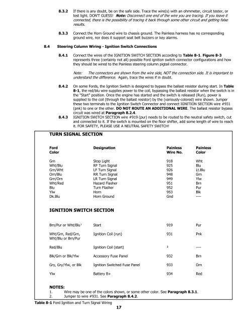
TURN SIGNAL SECTION<br />
<strong>For</strong>d Designation <strong>Painless</strong> <strong>Painless</strong><br />
Color <strong>Wire</strong> No. Color<br />
Grn Stop Light 918 Wht<br />
Wht/Blu RF Turn Signal 925 Blu<br />
Grn/Wht LF Turn Signal 926 Lt.Blu<br />
Orn/Blu RR Turn Signal 948 Grn<br />
Grn/Orn LR Turn Signal 949 Ylw<br />
Wht/Red Hazard Flasher 951 Brn<br />
Blu Turn Flasher 952 Pur<br />
Ylw Horn 953 Blk<br />
Dk.Blu Horn Ground Gnd ----<br />
IGNITION SWITCH SECTION<br />
Brn/Pur or Wht/Blu¹ Start 919 Pur<br />
Wht/Grn, Red/Grn, Ignition Coil (run) 931 Pnk<br />
Wht/Blu or Brn/Pur<br />
Red/Blu Ignition Coil (start) ² ----<br />
Blk/Grn or Blk/Ylw Accessory Fuse Panel 932 Brn<br />
Gry, Gry/Ylw, or Blk Ignition Switched Fuse Panel 933 Orn<br />
Ylw Battery B+ 934 Red<br />
NOTES:<br />
1. <strong>Wire</strong> may be one of the colors shown, or some other color. See Paragraph 8.3.1.<br />
2. Jumper to wire #931. See Paragraph 8.4.2.<br />
Table 8-1 <strong>For</strong>d Ignition and Turn Signal <strong>Wiring</strong><br />
17


