

Wire Harness Installation Instructions For Installing - Painless Wiring
Wire Harness Installation Instructions For Installing - Painless Wiring
Wire Harness Installation Instructions For Installing - Painless Wiring

You also want an ePaper? Increase the reach of your titles
YUMPU automatically turns print PDFs into web optimized ePapers that Google loves.
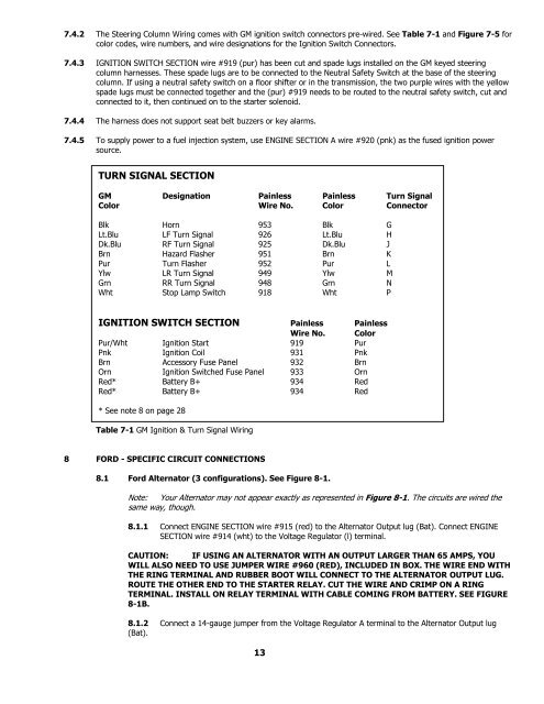
7.4.2 The Steering Column <strong>Wiring</strong> comes with GM ignition switch connectors pre-wired. See Table 7-1 and Figure 7-5 for<br />
color codes, wire numbers, and wire designations for the Ignition Switch Connectors.<br />
7.4.3 IGNITION SWITCH SECTION wire #919 (pur) has been cut and spade lugs installed on the GM keyed steering<br />
column harnesses. These spade lugs are to be connected to the Neutral Safety Switch at the base of the steering<br />
column. If using a neutral safety switch on a floor shifter or in the transmission, the two purple wires with the yellow<br />
spade lugs must be connected together and the (pur) #919 needs to be routed to the neutral safety switch, cut and<br />
connected to it, then continued on to the starter solenoid.<br />
7.4.4 The harness does not support seat belt buzzers or key alarms.<br />
7.4.5 To supply power to a fuel injection system, use ENGINE SECTION A wire #920 (pnk) as the fused ignition power<br />
source.<br />
TURN SIGNAL SECTION<br />
GM Designation <strong>Painless</strong> <strong>Painless</strong> Turn Signal<br />
Color <strong>Wire</strong> No. Color Connector<br />
Blk Horn 953 Blk G<br />
Lt.Blu LF Turn Signal 926 Lt.Blu H<br />
Dk.Blu RF Turn Signal 925 Dk.Blu J<br />
Brn Hazard Flasher 951 Brn K<br />
Pur Turn Flasher 952 Pur L<br />
Ylw LR Turn Signal 949 Ylw M<br />
Grn RR Turn Signal 948 Grn N<br />
Wht Stop Lamp Switch 918 Wht P<br />
IGNITION SWITCH SECTION <strong>Painless</strong> <strong>Painless</strong><br />
<strong>Wire</strong> No. Color<br />
Pur/Wht Ignition Start 919 Pur<br />
Pnk Ignition Coil 931 Pnk<br />
Brn Accessory Fuse Panel 932 Brn<br />
Orn Ignition Switched Fuse Panel 933 Orn<br />
Red* Battery B+ 934 Red<br />
Red* Battery B+ 934 Red<br />
* See note 8 on page 28<br />
Table 7-1 GM Ignition & Turn Signal <strong>Wiring</strong><br />
8 FORD - SPECIFIC CIRCUIT CONNECTIONS<br />
8.1 <strong>For</strong>d Alternator (3 configurations). See Figure 8-1.<br />
Note: Your Alternator may not appear exactly as represented in Figure 8-1. The circuits are wired the<br />
same way, though.<br />
8.1.1 Connect ENGINE SECTION wire #915 (red) to the Alternator Output lug (Bat). Connect ENGINE<br />
SECTION wire #914 (wht) to the Voltage Regulator (l) terminal.<br />
CAUTION: IF USING AN ALTERNATOR WITH AN OUTPUT LARGER THAN 65 AMPS, YOU<br />
WILL ALSO NEED TO USE JUMPER WIRE #960 (RED), INCLUDED IN BOX. THE WIRE END WITH<br />
THE RING TERMINAL AND RUBBER BOOT WILL CONNECT TO THE ALTERNATOR OUTPUT LUG.<br />
ROUTE THE OTHER END TO THE STARTER RELAY. CUT THE WIRE AND CRIMP ON A RING<br />
TERMINAL. INSTALL ON RELAY TERMINAL WITH CABLE COMING FROM BATTERY. SEE FIGURE<br />
8-1B.<br />
8.1.2 Connect a 14-gauge jumper from the Voltage Regulator A terminal to the Alternator Output lug<br />
(Bat).<br />
13


