

Wire Harness Installation Instructions For Installing - Painless Wiring
Wire Harness Installation Instructions For Installing - Painless Wiring
Wire Harness Installation Instructions For Installing - Painless Wiring

Create successful ePaper yourself
Turn your PDF publications into a flip-book with our unique Google optimized e-Paper software.
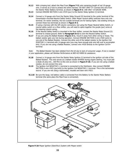
9.2.2 With crimping tool, attach the Maxi Fuse (Figure 7-3) onto remaining length of red 10-gauge<br />
wire. It serves as a fuse to protect the entire harness. DO NOT OMIT IT! Connect this wire from<br />
the Starter Motor Battery terminal, as shown in Figure 9-2. USE ONLY 10-GAUGE WIRE.<br />
9.2.3 Connect ENGINE SECTION A wire #919 (pur) to the Starter Relay Ignition (l) terminal.<br />
9.2.4 Connect a 14-gauge wire from the Starter Relay Ground (G) terminal to the center terminal of the<br />
transmission mounted Neutral Safety Switch. Older Mopar neutral safety switches have only one<br />
terminal. On newer switches, the two outside terminals are for backup lights. Use existing wiring to<br />
connect these two terminals as shown in Figure 9-2.<br />
9.2.5 If using a harness with the GM column connectors, but using the Mopar Neutral Safety Switch, or<br />
neutral safety switch on a floor shifter, you will need to splice together the purple (pur) wires at<br />
the steering column wiring.<br />
9.2.6 If the Neutral Safety Switch is mounted in the floor shifter, connect the Starter Relay Ground (G)<br />
terminal to chassis ground. Refer to Paragraph 9.4.2 to wire the Neutral Safety Switch.<br />
9.2.7 If you are using the Ballast Resistor (Figure 3-1), mount it away from other wiring or hoses. The<br />
ballast resistor gets very hot during operation. Connect ENGINE SECTION A wire #920 (pnk) to<br />
one end of the Ballast Resistor. Connect the other end of the ballast resistor to the Ignition Coil<br />
POSITIVE (+) terminal with 14-gauge wire (you may have enough pink wire left over to accomplish<br />
this). If you are not using a Ballast Resistor, connect wire #920 directly to the Ignition Coil B+<br />
terminal.<br />
Note: The Ballast Resistor has been deleted from this kit due to lack of consumer usage. If one is needed<br />
in your application, please call <strong>Painless</strong> Performance at 800-423-9696 for assistance.<br />
9.2.8 Connect a 14-gauge wire from the Starter Relay Ignition (l) terminal to the ignition coil side of the<br />
Ballast Resistor. This wire serves as a ballast resistor BYPASS during engine starting. You must add<br />
a diode (8 amp min., 100 PIV) to this wire as shown in Figure 9-2A. If you are not using a ballast<br />
resistor, do not connect this wire.<br />
9.2.9 The Ignition Coil NEGATIVE (-) terminal is connected to the Distributor. Also connect ENGINE<br />
SECTION A wire #923 (pur/wht) to the Ignition Coil NEGATIVE (-) terminal. This is the tachometer<br />
source. If you are not using a tachometer, insulate and stow wire #923.<br />
9.2.10 Be sure the large, red battery cable is connected from the Battery to the Starter Motor Battery<br />
terminal (the same place the Maxi Fuse is connected).<br />
Figure 9-2A Mopar Ignition (Start/Run) System with Mopar switch<br />
22


