

Wire Harness Installation Instructions For Installing - Painless Wiring
Wire Harness Installation Instructions For Installing - Painless Wiring
Wire Harness Installation Instructions For Installing - Painless Wiring

Create successful ePaper yourself
Turn your PDF publications into a flip-book with our unique Google optimized e-Paper software.
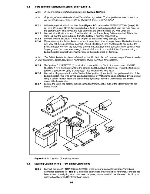
8.2 <strong>For</strong>d Ignition (Start/Run) System. See Figure 8-2.<br />
Note:<br />
Note:<br />
If you are going to install an ammeter, see Section 10.3 first.<br />
Original ignition module wire should be retained if possible. If your ignition harness connections<br />
are not salvageable, <strong>Painless</strong> offers a Duraspark harness, part # 30812<br />
8.2.1 With crimping tool, attach the Maxi Fuse (Figure 7-3) onto end of ENGINE SECTION (single) 10<br />
ga. wire #916 (red) AFTER having routed wire (with or without ammeter) from the Fuse Panel to<br />
the Starter Relay. This serves as a fuse to protect the entire harness. DO NOT OMIT IT!<br />
8.2.2 Connect wire #916 - with Maxi Fuse installed - to the Starter Relay Battery terminal. This is the<br />
same lug that the large red cable from the battery is normally connected to.<br />
8.2.3 Connect ENGINE SECTION A wire #919 (pur) to the Starter Relay Start (S) terminal.<br />
8.2.4 If you are using the Ballast Resistor, mount it away from other wiring or hoses. The Ballast Resistor<br />
gets very hot during operation. Connect ENGINE SECTION A wire #920 (pnk) to one end of the<br />
Ballast Resistor. Connect the other end of the Ballast Resistor to the Ignition Coil B+ terminal with<br />
14-gauge wire (you may have enough pink wire left over to accomplish this). If you are using a<br />
Ballast Resistor, connect wire #920 directly to the Ignition Coil B+ terminal.<br />
Note: The Ballast Resistor has been deleted from this kit due to lack of consumer usage. If one is needed<br />
in your application, please call <strong>Painless</strong> Performance at 800-423-9696 for assistance.<br />
8.2.5 The Ignition Coil NEGATIVE (-) terminal is connected to the Distributor. Also connect ENGINE<br />
SECTION A wire #923 (pur/wht) to the Ignition Coil NEGATIVE (-) terminal. This is the tachometer<br />
source. If you are not using a tachometer, insulate and stow wire #923.<br />
8.2.6 Connect a 14-gauge wire from the Starter Relay Ignition (l) terminal to the ignition coil side of the<br />
Ballast Resistor. This wire serves as a ballast resistor BYPASS during engine starting. If you are not<br />
using a ballast resistor, leave the Starter Relay Ignition (l) terminal unconnected and do not<br />
connect the bypass wire.<br />
8.2.7 Be sure the large, red battery cable is connected from the other side of the Starter Relay to the<br />
Starter Motor.<br />
Figure 8-2 <strong>For</strong>d Ignition (Start/Run) System<br />
8.3 Steering Column <strong>Wiring</strong> - Turn Signal Connections<br />
8.3.1 Connect the nine (9) TURN SIGNAL SECTION wires to your automobile's existing Turn Signal<br />
Connector according to Table 8-1. <strong>For</strong>d wire color codes are provided for reference. <strong>For</strong>d has not<br />
been uniform in assigning wire colors over the years; so you may find that the wire colors in your<br />
existing <strong>For</strong>d harness differ from those shown.<br />
16


