

Wire Harness Installation Instructions For Installing - Painless Wiring
Wire Harness Installation Instructions For Installing - Painless Wiring
Wire Harness Installation Instructions For Installing - Painless Wiring

You also want an ePaper? Increase the reach of your titles
YUMPU automatically turns print PDFs into web optimized ePapers that Google loves.
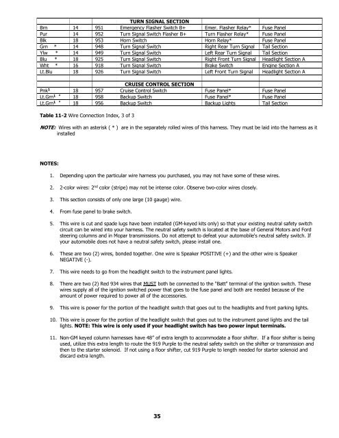
TURN SIGNAL SECTION<br />
Brn 14 951 Emergency Flasher Switch B+ Emer. Flasher Relay* Fuse Panel<br />
Pur 14 952 Turn Signal Switch Flasher B+ Turn Flasher Relay* Fuse Panel<br />
Blk 18 953 Horn Switch Horn Relay* Fuse Panel<br />
Grn * 14 948 Turn Signal Switch Right Rear Turn Signal Tail Section<br />
Ylw * 14 949 Turn Signal Switch Left Rear Turn Signal Tail Section<br />
Blu * 18 925 Turn Signal Switch Right Front Turn Signal Headlight Section A<br />
Wht * 16 918 Turn Signal Switch Brake Switch Engine Section A<br />
Lt.Blu 18 926 Turn Signal Switch Left Front Turn Signal Headlight Section A<br />
CRUISE CONTROL SECTION<br />
Pnk 1 18 957 Cruise Control Switch Fuse Panel* Fuse Panel<br />
Lt.Grn 1 * 18 958 Backup Switch Fuse Panel* Fuse Panel<br />
Lt.Grn 1 * 18 956 Backup Switch Backup Lights Tail Section<br />
Table 11-2 <strong>Wire</strong> Connection Index, 3 of 3<br />
NOTE: <strong>Wire</strong>s with an asterisk ( * ) are in the separately rolled wires of this harness. They must be laid into the harness as it<br />
installed<br />
NOTES:<br />
1. Depending upon the particular wire harness you purchased, you may not have some of these wires.<br />
2. 2-color wires: 2 nd color (stripe) may not be intense color. Observe two-color wires closely.<br />
3. This section consists of only one large (10 gauge) wire.<br />
4. From fuse panel to brake switch.<br />
5. This wire is cut and spade lugs have been installed (GM-keyed kits only) so that your existing neutral safety switch<br />
circuit can be wired into your harness. The neutral safety switch is located at the base of General Motors and <strong>For</strong>d<br />
steering columns and in Mopar transmissions. Do not attempt to defeat your automobile's neutral safety switch. If<br />
your automobile does not have a neutral safety switch, please install one.<br />
6. These are two (2) wires, bonded together. One wire is Speaker POSITIVE (+) and the other wire is Speaker<br />
NEGATIVE (-).<br />
7. This wire needs to go from the headlight switch to the instrument panel lights.<br />
8. There are two (2) Red 934 wires that MUST both be connected to the "Batt" terminal of the ignition switch. These<br />
wires supply all of the ignition switched power that goes to the fuse panel and both are needed because of the<br />
amount of power required to power all of the accessories.<br />
9. This wire is power for the portion of the headlight switch that goes out to the headlights and front parking lights.<br />
10. This wire is power for the portion of the headlight switch that goes out to the instrument panel lights and the tail<br />
lights. NOTE: This wire is only used if your headlight switch has two power input terminals.<br />
11. Non-GM keyed column harnesses have 48” of extra length to accommodate a floor shifter. If a floor shifter is being<br />
used, utilize this extra length to route the 919 Purple to the neutral safety switch on the shifter or transmission and<br />
then to the starter solenoid. If not using a floor shifter, cut 919 Purple to length needed for starter solenoid and<br />
discard extra length.<br />
35


