
Create successful ePaper yourself
Turn your PDF publications into a flip-book with our unique Google optimized e-Paper software.
2 Input Data<br />
Design of<br />
The design can be carried out for Members as well as for Sets of members. If you want to<br />
design only selected objects, clear the All check boxes. Then you can access the two input<br />
fields to enter the numbers of the relevant members or sets of members. To select the objects<br />
graphically in the <strong>RF</strong>EM work window, use the [Pick] button. The list of the preset<br />
member numbers can be selected quickly by double click and overwritten by entering the<br />
data manually.<br />
In case no set of members has yet been defined in <strong>RF</strong>EM, you can create a new set of members<br />
in <strong>RF</strong>-<strong>TIMBER</strong> <strong>Pro</strong> by using the [New] button. The dialog box that you already know<br />
from <strong>RF</strong>EM appears where you can specify the data for a new set of members.<br />
When you design a set of members, the program determines the extreme values of the designs<br />
of all members contained in the set of members and takes into account the boundary<br />
conditions of connected members for the stability analysis. Subsequent to the calculation,<br />
the additional results tables 2.3 Design by Set of Members, 3.2 Governing Internal Forces by<br />
Set of Members and 4.2 Parts List by Set of Members will be displayed.<br />
According to Code / Annex<br />
In the selection field on the top right, you specify the standard by which you want to perform<br />
the design. The following codes can be selected:<br />
• DIN 1052:2008-12<br />
• EN 1995-1:2004-11<br />
• SIA 265:2003<br />
When you select the European standard Eurocode 5, you also have to specify the national<br />
annex whose parameters will be used for the design and the deformation's limit values.<br />
Use the [Edit] button to open a dialog box where you can check and adjust, if necessary,<br />
the parameters of the standard or the currently selected NA. The dialog box is described in<br />
chapter 2.1.4 on page 12.<br />
Existing Load Cases / Load Groups and Load Combinations<br />
These two dialog sections list all load cases, groups and combinations defined in <strong>RF</strong>EM that<br />
are relevant for the design. Use the button [] to transfer selected load cases, groups or<br />
combinations to the list Selected for Design on the right. You can also double-click the<br />
items. To transfer the complete list to the right, use the button [].<br />
When load cases or combinations are marked by an asterisk (*) like load case 11 in Figure<br />
2.1, they cannot be calculated. Those load cases are cases without load data or pure imperfection<br />
cases.<br />
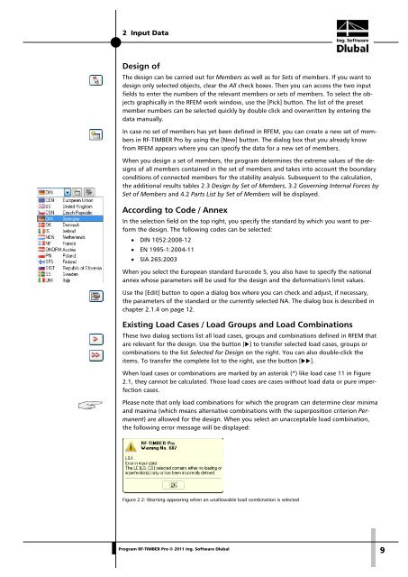
Please note that only load combinations for which the program can determine clear minima<br />
and maxima (which means alternative combinations with the superposition criterion Permanent)<br />
are allowed for the design. When you select an unacceptable load combination,<br />
the following error message will be displayed:<br />
Figure 2.2: Warning appearing when an unallowable load combination is selected<br />
<strong>Pro</strong>gram <strong>RF</strong>-<strong>TIMBER</strong> <strong>Pro</strong> © 2011 Ing. <strong>Software</strong> <strong>Dlubal</strong><br />
9